
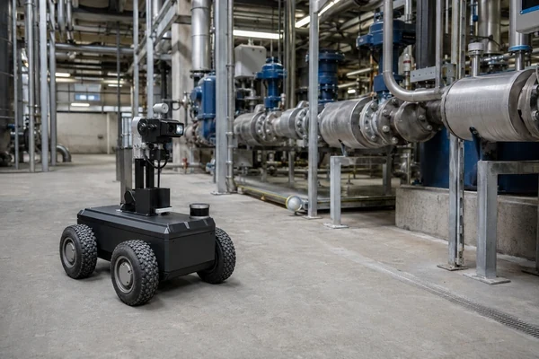
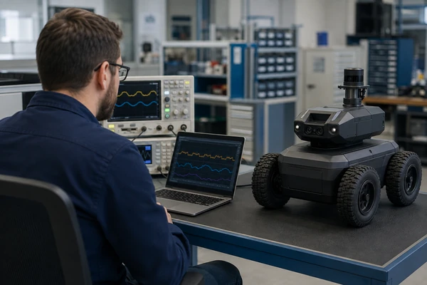
An inspection robot can carry enough nominal battery capacity to drive for hours and still fail its mission if the pack cannot simultaneously support traction, cameras, thermal imaging, LiDAR, environmental sensing, wireless communication and onboard computing.
For an industrial inspection platform, battery design is therefore a mission-level engineering problem—not simply an Ah specification.
The pack has to store enough usable energy to complete the inspection and, where necessary, return the robot safely. At the same time, it must support motor transients, continuous sensor and computing loads, charging requirements, vibration, temperature changes and the mechanical constraints of the robot.
Featured Snippet: What Battery Is Suitable for an Industrial Inspection Robot?
An industrial inspection robot typically requires a rechargeable lithium battery pack selected around system voltage, mission runtime, traction and sensor loads, peak power, environment, charging strategy, space, weight and safety requirements. 18650, 21700, LiFePO₄ and prismatic architectures can all be suitable. The correct inspection robot battery should be validated with the complete robot, including motors, sensors, computing, BMS, charger and any applicable hazardous-location requirements.
Industrial inspection platforms illustrate why this system-level approach matters. Published pipeline and mining robot designs combine drive motors with cameras, LiDAR, thermal imaging, gas or environmental sensing, computing and communications rather than using battery energy for locomotion alone.
Table of Contents
- Why Do Inspection Robots Create a Unique Battery Design Problem?
- How Should Engineers Design the Battery Pack Around the Inspection Mission?
- How Do Battery Requirements Change Across Inspection Environments?
- What Should OEMs Specify Before Developing a Custom Inspection Robot Battery?
1. Why Do Inspection Robots Create a Unique Battery Design Problem?
An inspection robot battery usually powers several very different electrical subsystems at the same time.
Depending on the application, the robot may carry:
- Drive motors
- Motor controllers
- Visible-light cameras
- Thermal cameras
- LiDAR or laser scanners
- Gas sensors
- Temperature and humidity sensors
- Vibration or acoustic sensors
- Illumination
- Wireless communications
- Navigation electronics
- CPU / GPU computing
- Data storage
A large-diameter in-pipe inspection robot described in engineering research, for example, incorporates multiple drive motors, cameras, LiDAR, wireless communication, inspection hardware and onboard batteries. [1]Underground mine patrol robots can combine LiDAR and navigation hardware with RGB-D imaging, thermal cameras, gas sensors and dust sensors. [2]
The battery is therefore supporting an entire inspection platform, not merely a moving chassis.
Traction and Inspection Payloads Create Different Load Profiles
Traction loads are often dynamic.
Motor current can increase when the robot:
- Accelerates
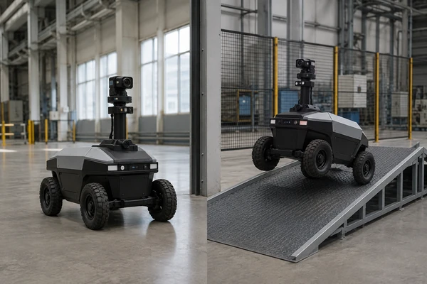
- Climbs an incline
- Crosses an obstacle
- Turns sharply
- Moves through debris
- Encounters higher rolling resistance
- Carries a heavier inspection payload
The inspection payload can create a different electrical pattern.
Cameras, LiDAR, thermal imaging, gas sensors, illumination, wireless links and onboard computers may remain active for long periods of the mission. These loads may not have the same large transients as the drive system, but they continuously consume energy.
A useful way to think about the battery load is:
Traction
Inspection Sensors
Navigation and Computing
Communication
Auxiliary Electronics
=
Complete Mission Power Profile
The highest battery demand may occur when several of these subsystems operate simultaneously.
For example, a robot may be climbing a slope while LiDAR remains active, a thermal camera records data, the processor performs localization and a wireless radio transmits inspection information.
Battery qualification should therefore use combined system loads rather than testing the traction system and sensor payload as completely separate problems.
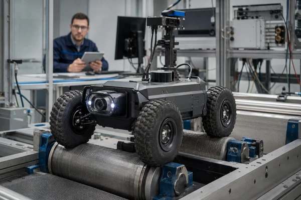
Mission Runtime Is More Important Than the Highest Ah Number
For an inspection robot, runtime should be linked to the mission.
OEMs should define:
- Travel time to the inspection area
- Active inspection time
- Stationary sensing periods
- Return-to-base time
- Expected terrain
- Payload configuration
- Communication duty cycle
- Required reserve energy
A battery with more Ah may extend theoretical runtime, but increasing capacity can also increase:
- Weight
- Volume
- Charging time
- Chassis load
- Mechanical integration difficulty
The correct objective is not:
Fit the largest battery possible.
It is:
Carry enough usable energy to complete the intended mission with an appropriate reserve while remaining within the robot’s mass, size and performance limits.
This becomes especially important for inspection systems operating inside pipelines, tunnels or other areas where recovering a robot after battery depletion could be difficult.
Energy Requirement and Peak-Power Requirement Are Different
Battery energy can be expressed in watt-hours:
Battery Energy (Wh) = Nominal Voltage (V) × Capacity (Ah)
For a deeper explanation of rechargeable cell chemistry, voltage behavior and real-world battery performance, see LONGSING’s lithium-ion battery guide.
A first-order runtime estimate is:
Estimated Runtime ≈ Usable Battery Energy ÷ Average System Power
This is useful for calculating how much energy the robot needs across a mission.
But the battery must also satisfy a separate power requirement.
Suppose the robot contains enough stored energy for several hours of operation. During an obstacle crossing, however, several traction motors may demand much higher current.
If the battery cannot support that load, the system may experience:
- Excessive voltage sag
- BMS overcurrent protection
- Motor-controller undervoltage
- Computer reset
- Communication interruption
- Mission abort
This leads to a fundamental inspection-robot battery principle:
Usable Wh determines how long the robot can work. Continuous and transient power capability determines whether it can successfully perform the most demanding parts of the mission.
OEMs should therefore provide both:
Average / continuous load
and
Peak current + peak duration + repetition frequency
when developing the battery specification.
Harsh Operating Environments Add a Mechanical Problem
Industrial inspection robots may operate in:
- Oil and gas facilities
- Petrochemical plants
- Pipelines
- Electrical substations
- Utility tunnels
- Underground mines
- Industrial processing facilities
- Outdoor infrastructure
Battery performance must therefore be considered together with exposure to:
- Dust
- Moisture
- Mud
- Vibration
- Mechanical shock
- Uneven terrain
- Seasonal temperature changes
The pack is not simply an electrical component placed inside a robot.
It becomes part of the robot’s mechanical and environmental system.For the broader relationship between drive loads, onboard computing and battery-system architecture across robotics, see LONGSING’s Industrial Robot Battery Solutions guide.
2. How Should Engineers Design the Battery Pack Around the Inspection Mission?
The battery should be designed from the robot’s voltage window, mission energy, maximum traction load, sensor and computing consumption, mechanical envelope and charging strategy before a specific lithium chemistry or cell size is selected.
Start With the System Voltage Architecture
There is no universal inspection-robot battery voltage.
Depending on the motor, controller and power-conversion architecture, inspection robots may use 24V-class battery packs, 36V battery packs, 48V battery packs or another voltage architecture.
The OEM should first define:
- Nominal battery voltage
- Fully charged voltage
- Minimum operating voltage
- Motor-controller voltage range
- Maximum system load
- DC/DC converter input requirements
- Battery protection cut-off limits
A 48V inspection robot battery may be appropriate for a platform designed around a 48V-class drive system, but this does not mean every inspection robot should use 48V.
The correct sequence is:
Robot electrical architecture
→
Required battery voltage
→
Series-cell configuration
not:
Choose a common battery voltage
→
Force the robot architecture around it
Build an Inspection Mission Energy Budget
Instead of using one generic average-current estimate, divide the robot into functional load groups.
| Load Group | Engineering Questions |
|---|---|
| Traction | What is average drive power? What happens on slopes or obstacles? |
| Cameras / Thermal Imaging | Which imaging systems operate continuously? |
| LiDAR / Sensors | How many sensors operate and at what duty cycle? |
| Computing | What is the average and highest processing load? |
| Communication | Is the radio continuous, periodic or event-driven? |
| Lighting | Is illumination continuous or triggered only during inspection? |
| Reserve Energy | How much energy must remain for return-to-base or recovery? |
The final battery energy target should include appropriate engineering reserve.
A mission plan that mathematically consumes nearly 100% of nominal battery energy provides little tolerance for:
- Temperature
- Battery aging
- Conversion losses
- Unexpected obstacles
- Longer inspection time
- Communication retries
- Mission changes
Define Continuous and Peak Power Separately
Inspection platforms commonly combine relatively continuous electronics loads with rapidly changing traction demand.
The OEM should provide:
- Average current
- Maximum continuous current
- Peak traction current
- Peak duration
- Peak repetition frequency
- Minimum allowable system voltage
- Worst simultaneous subsystem load
The battery should then be evaluated under conditions representative of the real robot.
That should include more than:
fresh battery + full SOC + room temperature
Relevant validation points can include:
- Partial SOC
- Repeated acceleration
- Incline operation
- Continuous sensor load
- Simultaneous sensor + motor operation
- Relevant low or elevated temperatures
Which Cell Chemistry or Format Fits the Robot?
There is no universal best choice.
Selection should consider:
- Required energy
- Peak power
- Voltage
- Installation space
- Weight
- Cycle-life target
- Temperature
- Charging strategy
- Mechanical packaging
- Safety architecture
18650 Lithium-Ion Cells
18650 lithium-ion cells can provide a flexible cylindrical architecture for custom inspection robot battery packs.
They may be appropriate when the OEM requires:
- Configurable series/parallel arrangements
- Compact cylindrical packaging
- Flexible battery geometry
- A balance of energy and power suited to the selected cell
For some robots, multiple smaller cylindrical cells can make it easier to distribute battery mass within the chassis.
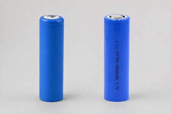
21700 Lithium-Ion Cells
21700 lithium-ion cells provide another cylindrical option for inspection robot battery design.
Depending on the selected cell, a 21700 architecture may change:
- Cell count
- Pack energy
- Current capability
- Mechanical volume
- Thermal layout
The decision should be made at pack level, not by assuming that a larger cylindrical cell is automatically better.
LiFePO₄
LiFePO₄ prismatic cells can be evaluated where their voltage, lifecycle, thermal, packaging and safety characteristics fit the inspection system.
However, it may also create different:
- Voltage architecture
- Energy-density trade-offs
- Pack dimensions
- Weight
- Charging requirements
It should therefore not automatically be described as the best chemistry for industrial robots.
Prismatic Lithium Cells
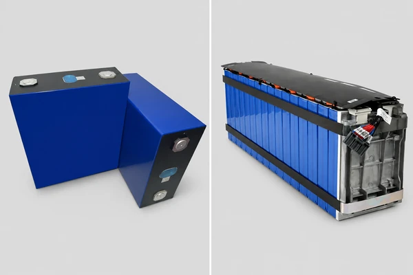
Where a rectangular battery compartment or larger cell format provides a better mechanical fit, custom prismatic battery packs can be evaluated around the robot’s voltage, capacity, BMS, enclosure and installation constraints.
- The battery compartment is rectangular
- A larger cell format simplifies pack assembly
- Chassis volume favors flat or block-shaped battery packaging
Again, mechanical geometry does not replace electrical qualification.
The robot defines the battery architecture. The battery cell format should not define the robot.
Smart BMS Functions Should Match the Mission
A rechargeable multi-cell inspection robot pack generally requires an appropriate BMS and protection architecture.
Depending on the system, functions may include:
- Cell-voltage monitoring
- Pack-current monitoring
- Temperature monitoring
- Overcharge protection
- Over-discharge protection
- Overcurrent protection
- Short-circuit protection
- Cell balancing
- State of Charge estimation
- State of Health information where required
- Fault reporting
Industrial mobile-robot BMS architectures commonly combine cell monitoring, voltage/current/temperature protection, balancing and battery gauging. [3]
However, the exact feature set should be based on the inspection platform rather than copied from another robot application.
When Does Battery Communication Matter?
Some robots need the battery to exchange information with the main controller or charger:
Battery
↕
Robot Controller
↕
Charger
Relevant data may include:
- SOC
- Pack voltage
- Pack current
- Temperature
- Warning status
- Fault state
- Charge permission
- Pack identification
CAN can be useful in some industrial platforms, but CAN is not mandatory for every inspection robot.
Where CAN is required, the OEM should specify:
- Bitrate
- Message IDs
- Message cycle time
- Data definitions
- Scaling
- Warning flags
- Fault flags
- Communication timeout
- Charger messages
- Startup behavior
Simply specifying:
“Smart BMS with CAN”
does not define a usable communication interface.
For a deeper comparison of communication architecture, see LONGSING’s CAN vs RS485 BMS engineering guide. The key point for an inspection robot is that the battery interface must match the controller, charger, message map and fault-handling requirements.
Charging Architecture Should Follow Mission Uptime
For additional engineering guidance on CC-CV charging, charging voltage, current limits and temperature considerations, see LONGSING’s Lithium Ion Battery Charging Basics.
There are several possible charging strategies.
Automatic Docking
Docking can suit a robot that performs recurring patrol or inspection routes and can return to a fixed charging station.
The design must consider:
- Dock alignment
- Charging contacts
- Charger detection
- BMS state
- Charge control
- Robot scheduling
Opportunity Charging
The robot charges during planned idle periods.
This may reduce the energy that needs to be carried for each mission but increases dependence on:
- Charger availability
- Charge scheduling
- Thermal management
- Reliable docking
Swappable Battery
A swappable inspection robot battery may suit missions where downtime must be minimized.
The battery and robot then need:
- Robust pack retention
- Durable power connectors
- Safe disconnect
- Battery identification
- Operator-friendly handling
- SOC tracking between packs
Manual Charging
Manual charging may be completely appropriate where inspection frequency is low and continuous availability is not required.
There is no engineering advantage in adding an automatic dock simply because the robot is autonomous.
Charging architecture should follow the operational workflow.
3. How Do Battery Requirements Change Across Inspection Environments?
Different inspection scenarios can have very different battery priorities.
Inspection Robot Battery Requirements by Scenario
| Inspection Scenario | Environment | Main Electrical Loads | Battery Priority | Charging Approach | Important Design Consideration |
|---|---|---|---|---|---|
| Oil & gas / petrochemical inspection | Industrial areas; classified locations may exist | Traction, cameras, thermal imaging, gas sensing, computing, communication | Mission energy + system safety | Docking, swapping or manual charging | Hazardous-location certification may affect the complete robot architecture |
| Pipeline inspection | Confined space, long routes, uneven pipe surfaces | Traction, cameras, LiDAR, NDT sensors, communications | Mission completion + return reserve | Removable pack or recharge between missions | Recovery may be difficult after battery depletion |
| Power utility inspection | Substations, cable tunnels, mixed outdoor conditions | Visual/thermal cameras, LiDAR, computing, communications | Runtime + stable sensor power | Docking / scheduled charging | Weather, enclosure and communication integration |
| Tunnel / mining inspection | Dust, moisture, slopes, vibration, potentially hazardous atmospheres | Traction, lighting, thermal imaging, gas sensing, LiDAR | Ruggedness + peak power + runtime | Swapping or docking | Mechanical shock, contamination and possible HazLoc constraints |
| Industrial facility patrol | Factories and mixed indoor environments | Traction, visual/thermal inspection, computing, wireless communication | Availability + flexible integration | Docking or opportunity charging | Integration with patrol schedules and host systems |
Mining inspection research demonstrates the diversity of payloads involved: autonomous platforms can combine LiDAR and inertial navigation with RGB-D imaging, gas sensors, particle detection and thermal cameras.
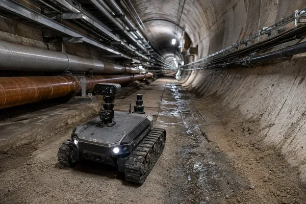
Power-system inspection robots likewise use sensor fusion involving LiDAR and visual information for navigation and environmental understanding.[4]
Environmental Protection Must Be Specified at Enclosure Level
Terms such as:
waterproof robot battery
or
dustproof battery
are not sufficiently precise engineering requirements.
IEC 60529 defines the IP Code for degrees of protection provided by electrical-equipment enclosures. [5]
An OEM should instead define the actual environmental target and design:
- Pack enclosure
- Seals
- Cable entries
- Connector interfaces
- Enclosure joints
- Condensation management
- Service openings
- Pressure equalization where required
A specific IP rating such as IP65 or IP67 should only be claimed when the relevant enclosure has actually been designed and validated to that requirement.
A cell specification does not create an enclosure IP rating.
Vibration and Shock Must Be Managed Through Pack Construction
Tracks, wheels, pipeline contact and obstacle crossings can transfer repeated mechanical loads into the battery.
Mechanical design should therefore consider:
- Cell restraint
- Cell holders
- Pack mounting
- Busbar integrity
- Weld integrity
- PCB/BMS fixation
- Connector retention
- Cable strain relief
- Enclosure stiffness
- Weight distribution
For a mobile inspection system, battery construction should be evaluated together with the robot chassis.
Thermal Management Includes Both Operation and Charging
Battery temperature is affected by:
- Ambient temperature
- Internal cell resistance
- Discharge current
- Charging current
- Nearby motor controllers
- Computing electronics
- Enclosure heat rejection
OEMs should distinguish between:
robot operating temperature
and
battery charging temperature
because the acceptable charging conditions of the selected lithium cells may differ from their discharge conditions.
BMS temperature sensing should also be located where it provides meaningful information about the actual cells or pack.
A sensor mounted only where convenient on the PCB may not represent the hottest or coldest part of the battery.
Hazardous-Location Inspection Robots Require System-Level Certification
For some oil and gas, petrochemical, mining and energy applications, the inspection environment may contain combustible gases, vapors or dust.
This changes the engineering problem significantly.
In June 2026, UL Solutions introduced its UL 6260 certification program for remotely operated inspection and maintenance robots and drones used in hazardous locations. UL describes the scope as including rechargeable-battery-powered platforms and states that HazLoc evaluation can address fire, explosion, electric shock, mechanical risks and hazardous-location protection. UL Solutions also announced its first UL 6260 robot certification in June 2026. [6]
This has an important implication for battery design:
A normal lithium battery does not become suitable for a hazardous location simply because it uses a particular chemistry, a metal enclosure or a BMS.
Hazardous-location compliance is a complete system engineering and certification problem.
Depending on the target classification and certification pathway, the design may need to address:
- Possible ignition sources
- Battery fault conditions
- Electrical faults
- Surface temperatures
- Connectors
- Switching devices
- Enclosure design
- Mechanical impact
- Charging
- Explosion-protection concepts
- Fault behavior
UL 6260 covers remotely operated inspection and maintenance equipment used in hazardous locations, including rechargeable-battery systems and different robotic mobility types.
LONGSING should therefore not describe an inspection robot battery as:
- UL 6260 certified
- Explosion-proof
- Intrinsically safe
- HazLoc certified
unless that exact status has been formally verified for the applicable product.
Similarly:
LiFePO₄ ≠ automatically HazLoc suitable
and
Smart BMS ≠ intrinsically safe system
For an oil-and-gas or hazardous-location robot project, certification requirements need to be defined early enough to influence battery, enclosure, wiring, connectors and charging architecture.
4. What Should OEMs Specify Before Developing a Custom Inspection Robot Battery?
A useful battery RFQ should describe the complete inspection mission.
A request such as:
“We need a 48V 30Ah inspection robot battery.”
still leaves many critical design questions unanswered.
Electrical Requirements
Provide:
- Nominal battery voltage
- Maximum operating voltage
- Minimum operating voltage
- Average current or system power
- Maximum continuous current
- Traction peak current
- Peak duration
- Peak repetition rate
- Motor-controller requirements
- DC/DC converter requirements
Where possible, provide a measured:
Current vs Time
or
Power vs Time
profile from a representative robot mission.
Mission Requirements
Provide:
- Mission duration
- Travel distance
- Inspection duration
- Inspection dwell periods
- Expected terrain
- Return-to-base requirement
- Reserve SOC target
- Mission frequency
The battery supplier needs to know whether the stated runtime means:
“three hours until complete discharge”
or:
“two hours of inspection plus a guaranteed return mission and reserve.”
These are different battery specifications.
Sensor and Computing Configuration
List the major loads, including:
- Visible cameras
- Thermal cameras
- LiDAR
- Laser scanners
- Gas sensors
- Vibration sensors
- Acoustic sensors
- Illumination
- Wireless radios
- Main processor
- GPU / AI computing platform
This allows the battery designer to understand what portion of the mission energy is consumed independently of vehicle movement.
Mechanical Requirements
Provide:
- Maximum battery dimensions
- Available installation volume
- Weight target
- Mounting location
- Mounting orientation
- Weight-distribution requirements
- Vibration conditions
- Shock requirements
- Connector location
- Cable routing
- Service method
- Fixed vs removable architecture
The selection between 18650, 21700, prismatic or another configuration may depend as much on these mechanical constraints as on nominal capacity.
Environmental Requirements
Provide:
- Minimum operating temperature
- Maximum operating temperature
- Charging temperature
- Dust exposure
- Moisture exposure
- Mud / contamination
- Cleaning requirements
- Enclosure target
- Required IP rating, if applicable
The enclosure target should be treated separately from cell specifications.
BMS Requirements
Define:
- Required protection functions
- SOC requirement
- SOH requirement, if any
- Temperature sensing
- Fault reporting
- Pack identification
- Diagnostic data
Do not add every possible BMS feature unless the robot needs it.
Communication Requirements
If battery communication is required, define the actual interface.
For CAN, provide:
- Bitrate
- Message IDs
- Message timing
- Data definitions
- Scaling
- Fault behavior
- Timeout behavior
- Charger communication
- Controller handshake
LONGSING’s CAN vs RS485 BMS guide can be used as an internal technical reference for this stage rather than duplicating the protocol discussion here.
Charging Requirements
Provide:
- Charging voltage
- Charger architecture
- Required charge time
- Maximum charging current
- Docking requirement
- Charge-while-operating requirement
- Swappable pack requirement
- Charging-temperature conditions
Charging should be developed with the battery rather than added after the robot design is completed.
Cell Matching and Pack Manufacturing
For a multi-cell inspection robot battery, pack behavior also depends on the consistency of the cells being assembled.
Relevant manufacturing checks can include:
- Capacity
- Open-circuit voltage
- Internal resistance / ACIR
- Initial SOC
- Self-discharge screening where applicable
For multi-cell packs, capacity, OCV and internal-resistance consistency also affect finished-pack behavior. LONGSING’s Battery Cell Matching guide explains the role of capacity, OCV and ACIR before pack assembly.
The key distinction is:
Cell matching happens before pack assembly. BMS balancing after assembly does not convert poorly matched cells into a properly matched battery pack.
Safety and Certification Requirements
OEMs should define the expected certification pathway as early as possible.
For industrial secondary lithium cells and batteries, IEC 62619:2022 specifies requirements and tests for secondary lithium batteries used in industrial applications and includes motive applications among its examples. [7]Whether it applies to a particular inspection robot should still be determined based on the actual product and certification pathway.
Other project requirements may include:
- Lithium battery transport requirements
- Market-specific equipment standards
- Enclosure requirements
- EMC requirements
- Hazardous-location certification
These requirements are not interchangeable.
A transport test does not certify the robot for operation in an explosive atmosphere, and a battery safety standard does not automatically certify the complete inspection robot.
Inspection Robot Battery Specification Checklist
| Parameter | Why It Matters |
|---|---|
| Nominal voltage | Defines battery series architecture |
| Operating-voltage range | Ensures compatibility with robot electronics |
| Minimum system voltage | Defines allowable voltage sag |
| Average system load | Drives mission-energy requirement |
| Traction peak current | Defines transient-power demand |
| Peak duration | Distinguishes short transient from sustained high load |
| Sensor / computing load | Adds continuous mission energy consumption |
| Mission runtime | Defines usable Wh target |
| Return reserve | Protects against depletion before mission recovery |
| Battery dimensions | Determines feasible pack architecture |
| Weight target | Influences mobility and chassis balance |
| Operating temperature | Affects battery performance |
| Charging temperature | Affects charging strategy |
| Vibration / shock | Influences mechanical pack construction |
| Enclosure requirement | Defines environmental integration |
| Charging method | Determines charger / pack interface |
| BMS requirements | Defines monitoring and protection architecture |
| Communication protocol | Determines controller and charger integration |
| Connector | Defines power, signal and mechanical interface |
| Target market | Influences certification planning |
| HazLoc requirement, if applicable | Can fundamentally affect system architecture and certification |
Where LONGSING Fits
LONGSING Website B focuses on rechargeable lithium batteries and custom lithium battery packs for industrial and professional equipment.
Depending on the actual inspection robot architecture, relevant LONGSING product directions can include:
- Custom lithium-ion battery packs
- 24V-class battery packs
- 36V battery packs
- 48V battery packs
- 18650 lithium-ion batteries
- 21700 lithium-ion batteries
- LiFePO₄ prismatic cells
- Custom prismatic battery packs
- BMS and communication integration
- Customized connectors and mechanical battery structures
These product directions should not be treated as predetermined solutions.
A more useful battery-development sequence is:
Inspection Mission
↓
System Voltage and Load Profile
↓
Usable Energy and Peak Power
↓
Cell Chemistry and Format
↓
BMS and Communication
↓
Charging Architecture
↓
Mechanical and Environmental Integration
↓
Safety / Certification Requirements
↓
Prototype and System Validation
Conclusion
A reliable inspection robot battery must support the entire inspection mission rather than mobility alone. Traction, cameras, thermal imaging, LiDAR, environmental sensing, communication and onboard computing create a mixed energy-and-power requirement that must be evaluated together.
Voltage, cell format, BMS, charging, enclosure and mechanical construction should then follow from that mission profile. For robots intended for hazardous locations, battery development must also fit the complete system-level certification strategy rather than relying on chemistry or BMS design alone.
B2B CTA
Developing an industrial inspection robot or remote inspection platform?
For a custom rechargeable battery evaluation, provide:
- System voltage
- Operating-voltage range
- Average load
- Traction peak current
- Peak duration
- Required mission runtime
- Return / reserve requirement
- Sensor and computing configuration
- Available battery dimensions
- Weight target
- Operating and charging temperature
- Vibration / environmental requirements
- Charging architecture
- BMS requirements
- Communication interface
- Connector requirements
- Target markets
- Applicable safety or hazardous-location requirements
These parameters allow the cell format, pack architecture, BMS, charging system, communication interface and mechanical structure to be evaluated against the real inspection mission rather than a generic robot battery specification.
Frequently Asked Questions About Inspection Robot Batteries
Click to explore more information about inspection robot battery design
Q: What type of battery is used in industrial inspection robots?
A: Rechargeable lithium battery packs are suitable for many inspection robots, but there is no universal chemistry or format. 18650, 21700, prismatic lithium-ion and LiFePO₄ architectures can all be considered depending on voltage, energy, power, space, weight, temperature, charging strategy and safety requirements.
Q: How do you calculate battery capacity for an inspection robot?
A: Start by estimating the energy consumed by traction, sensors, cameras, computing, communications and auxiliary systems across the complete mission. Average system power multiplied by mission duration provides a first estimate of required Wh. Conversion losses, reserve energy, aging and environmental conditions should then be considered. Peak traction current must be evaluated separately.
Q: Are 18650 or 21700 cells suitable for inspection robots?
A: Yes, when their electrical, thermal and mechanical characteristics fit the robot. 18650 and 21700 cells can both support custom series/parallel configurations, but the decision should be based on complete pack energy, current capability, space, weight and thermal design rather than individual-cell capacity alone.
Q: Is LiFePO₄ suitable for an industrial inspection robot?
A: It can be suitable for some inspection systems. Its cycle-life, voltage, thermal and safety characteristics may fit certain industrial applications, but its energy density, pack voltage and physical configuration create different trade-offs from other lithium-ion chemistries. It is not automatically the best option for every robot.
Q: Why does an inspection robot need a Smart BMS?
A: An appropriate BMS can monitor cell voltage, current and temperature and provide protection against overvoltage, undervoltage, overcurrent and short circuit. Depending on the system, it may also provide cell balancing, SOC estimation, diagnostics, fault reporting and communication with the robot controller or charger.
Q: How does CAN communication work between an inspection robot and the battery BMS?
A: CAN can allow a battery to exchange information such as SOC, voltage, current, temperature, warning states and faults with the robot controller or charger. The OEM still needs to define bitrate, message IDs, message frequency, data definitions, scaling and fault behavior. Specifying “CAN BMS” alone does not define the protocol.
Q: Should an inspection robot use docking charging or a swappable battery?
A: It depends on the inspection workflow. Automatic docking can suit recurring autonomous patrols, while swappable batteries can reduce downtime where rapid mission turnaround is required. Opportunity and manual charging can also be appropriate depending on mission frequency, infrastructure and thermal limits.
Q: Can a standard lithium battery be used in a hazardous-location inspection robot?
A: Not automatically. Hazardous-location operation requires system-level engineering and an applicable certification pathway. A particular lithium chemistry, BMS or enclosure does not by itself make the battery or robot explosion-proof, intrinsically safe or HazLoc certified. UL 6260 is one framework for remotely operated inspection and maintenance robots used in hazardous locations and evaluates the complete equipment, including relevant battery, electrical, mechanical, fire and explosion risks.
Reference: