
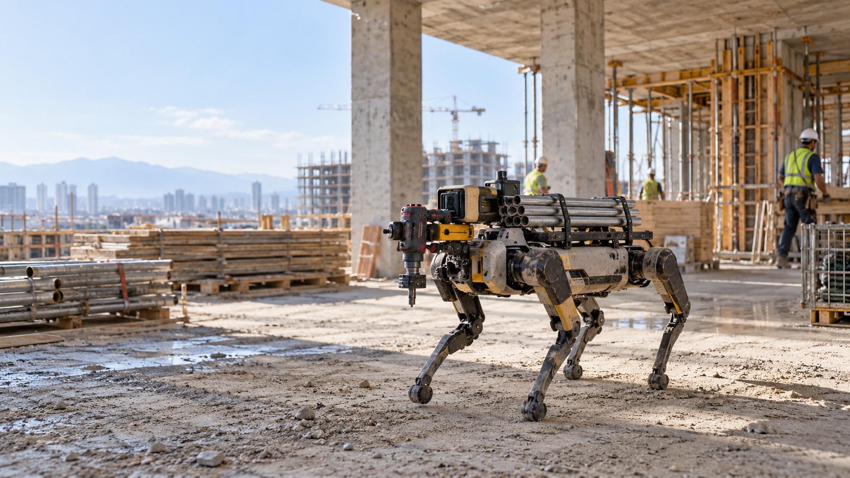
A construction robot may spend part of its shift standing still while mapping a work area, then move with a payload, climb an incline, reposition a robotic arm and operate a drill or fastening tool within the next few minutes. The battery sees very different electrical conditions during each of those states.
That variation is becoming easier to see in real machines. In October 2026, All3 disclosed specifications for its Mantis construction robot, a 135 kg electric quadruped designed to carry heavy loads, climb stairs and perform structural work. Its power system uses two hot-swappable battery packs, illustrating how battery architecture is increasingly being designed around jobsite uptime rather than capacity alone. [1]
A construction robot battery therefore has to satisfy several requirements at the same time:
Runtime ↔ Payload ↔ Peak Power ↔ Battery Weight ↔ Charging / Swap Time ↔ Fleet Uptime
Increasing battery capacity can extend stored energy, but the added battery mass may reduce available payload, alter the robot’s dynamics and occupy space needed for actuators, electronics or structural components.
The useful design question is not simply, “How many amp-hours does the robot need?” It is: “What battery architecture can support the robot’s complete working cycle without exceeding electrical, thermal, mechanical or operating constraints?”
A construction robot battery should be sized from the robot’s duty cycle, including usable energy, average and peak power, loaded voltage, payload, battery weight, thermal conditions, charging strategy and BMS communication. High-current events such as climbing, lifting and tool operation can cause voltage sag even when usable energy remains. Hot-swappable packs may improve fleet uptime where long charging interruptions are unacceptable.
Table of Contents
1. Why Construction Robot Battery Design Is Different
A construction robot battery has to support loads that are often separated in simpler mobile machines. A wheeled delivery robot may spend most of its energy on traction, computing and sensing. A construction platform can add a large manipulator, gripper, drilling system, fastening tool, lifting mechanism or another powered attachment on top of its locomotion system.
The electrical load can change according to the task:
- Standing or mapping: traction demand may be relatively low while computers, LiDAR, cameras and communications remain active.
- Driving or walking: multiple propulsion motors introduce a larger continuous load.
- Acceleration, climbing or stair movement: motor torque rises and current demand can increase sharply.
- Carrying materials: higher vehicle mass changes traction demand.
- Robotic-arm and tool operation: several actuators, a drill or fastening system may operate at the same time.
- Hot or cold jobsites: cell resistance, usable energy and thermal behavior change with temperature.
This matters because energy requirement and power requirement are separate specifications. A pack may contain enough watt-hours for the planned working period yet still fail during a brief high-current event. The opposite is also possible: a pack may deliver the required peak current easily but carry insufficient usable energy for the intended shift.
That distinction should be established before selecting chemistry, cell format or pack voltage. LONGSING’s industrial robot battery solutions article provides related system-level background for fixed and mobile industrial robotics.
2. Runtime Is More Than Battery Capacity
Construction robot battery energy is normally expressed in watt-hours:
Battery Energy (Wh) = Nominal Voltage (V) × Capacity (Ah)
A useful first-pass runtime relationship is:
Estimated Runtime ≈ Usable Battery Energy ÷ Average System Power
The phrase average system power is where most of the engineering work begins. Depending on the construction robot, the energy budget may include locomotion motors, steering or leg actuators, robotic-arm joints, grippers, electric tools, onboard computers, motor drives, LiDAR, cameras, GNSS, wireless communication, safety systems and thermal-management hardware.
Payload also changes the result. A robot carrying a tool and building material generally needs more mechanical work to accelerate, climb or negotiate uneven terrain than the same platform operating unloaded. On a legged platform, added mass may also change joint torque requirements and gait efficiency.
That is why two robots using batteries with the same nominal Wh can achieve very different runtime. Their terrain, payload, movement pattern, actuator duty cycle and auxiliary loads may be completely different.
Battery mass belongs in the same calculation. Adding cells increases stored energy, but those cells themselves become part of the load that the robot must move. For a heavy mobile construction robot, the design process should therefore evaluate the finished pack mass per usable Wh, not only nominal capacity.
3. Peak Power During Climbing, Lifting and Tool Operation
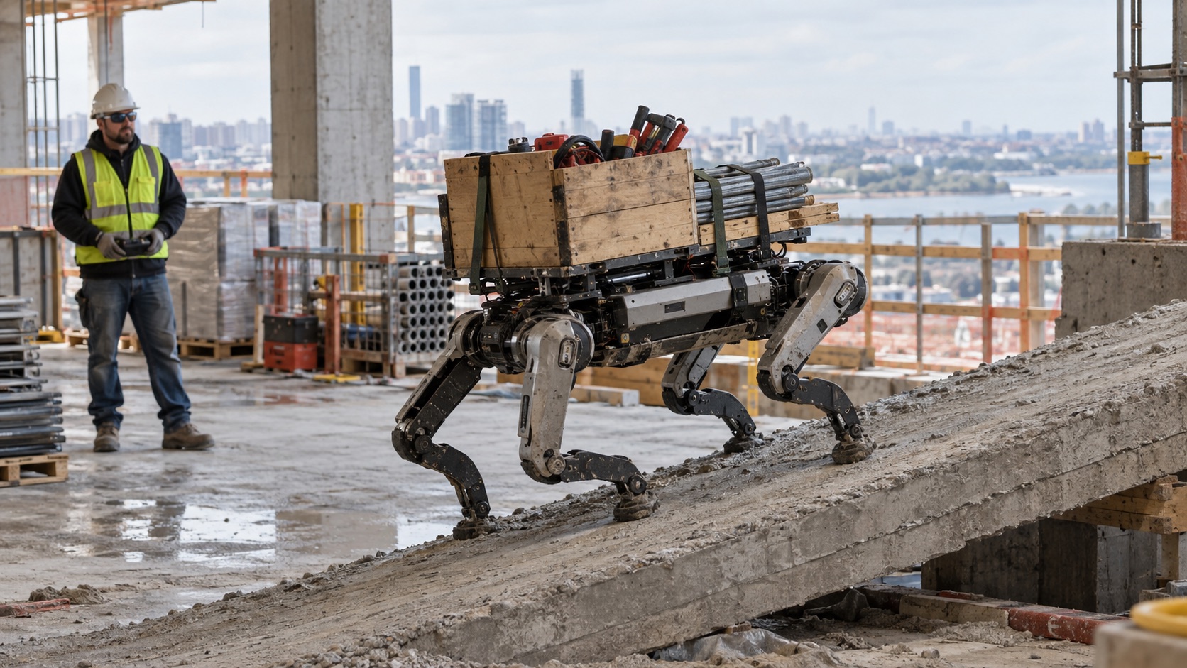
The largest battery load may occur for only a few seconds. Imagine a loaded mobile robot approaching a step or incline. Traction motors increase torque while a robotic arm holds equipment in position. If a powered tool starts at the same time, several loads can overlap.
The construction robot battery now sees a current demand far above the value measured during steady movement. A simple first-order relationship helps explain the resulting voltage drop:
Vload ≈ VOC − I × Rtotal
Equivalent-circuit battery models represent terminal voltage using open-circuit voltage, internal resistance and additional dynamic elements. Under discharge, the resistive term pulls terminal voltage below open-circuit voltage as current rises. [2]
In an actual robot, the effective current path includes more than the electrochemical cell:
Cells → Interconnections → Busbars → BMS / Contactors → Cables → Connectors → Motor Controller
Resistance anywhere along that path contributes to loaded-voltage loss. This creates a practical problem: the robot can reach its minimum DC-bus or BMS undervoltage limit even though the battery still contains usable energy.
A design based only on Wh may therefore appear correct during an energy calculation but fail during motor startup, stair climbing, high-torque turning, lifting, simultaneous actuator movement or tool startup.
Peak-current specification should define maximum expected current, peak duration, repetition frequency, simultaneous motor and actuator loading, minimum acceptable voltage under load and recovery time between peaks. Cell selection, parallel count, conductors, connectors and BMS limits must then be evaluated against the same transient load profile.
4. 18650 vs 21700 vs LiFePO₄ for Construction Robots
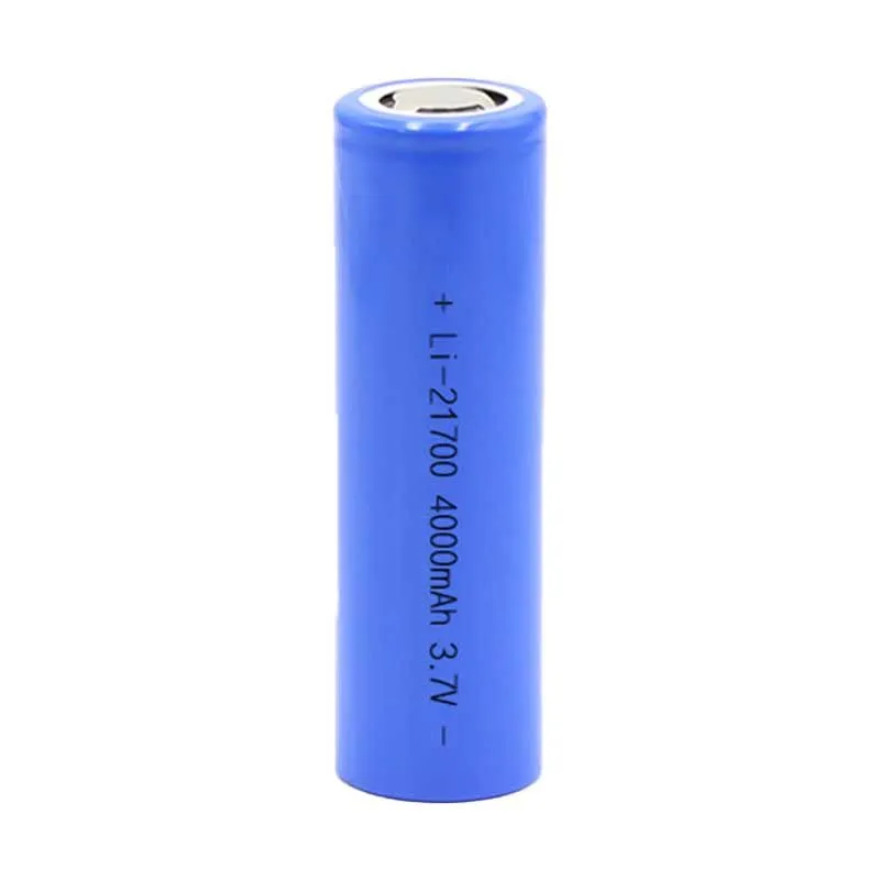
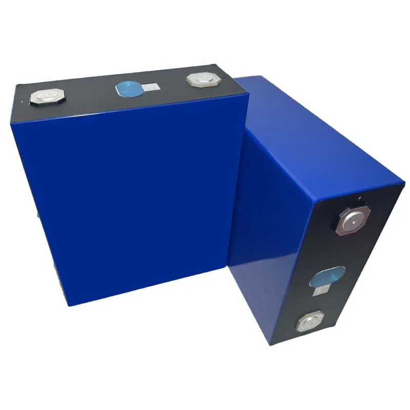
Construction robot battery selection requires one important clarification: 18650 and 21700 describe cylindrical cell formats. LiFePO₄ describes a battery chemistry. A LiFePO₄ cell may be cylindrical or prismatic, while 18650 and 21700 cells may use other lithium-ion chemistries.
The selection process should therefore separate chemistry selection from cell-format selection. LONGSING’s 18650 vs 21700 vs prismatic cells guide explains why cell architecture should be selected from complete pack requirements rather than single-cell capacity.
18650 vs 21700 vs LiFePO₄ for Construction Robot Battery Systems
| Engineering Factor | 18650 Lithium-Ion Architecture | 21700 Lithium-Ion Architecture | LiFePO₄-Based Architecture |
|---|---|---|---|
| What it describes | Cylindrical cell format | Larger cylindrical cell format | Cell chemistry; may use cylindrical or prismatic cells |
| Pack layout | High flexibility in irregular spaces | Cylindrical layout with larger individual cells | Depends strongly on selected cell format |
| Physical cell count | May require more cells for a given energy target | A suitable higher-capacity cell may reduce physical cell count | Large prismatic designs may use relatively few cells |
| Weight / energy | Depends on selected chemistry and cell | Depends on selected chemistry and cell | Must be evaluated from actual cell and pack data |
| Peak power | Depends on selected power cell and parallel count | Depends on selected power cell and parallel count | Depends on selected LiFePO₄ cell and architecture |
| Mechanical integration | Many smaller cells, holders and interconnections | Similar cylindrical architecture with fewer potential assembly points | Prismatic designs require appropriate restraint and busbar design |
| Thermal design | Many distributed heat sources | Fewer, larger cylindrical heat sources may change heat flow | Strongly dependent on cell size, spacing and cooling interface |
| Cycle-life target | Cell- and duty-cycle-dependent | Cell- and duty-cycle-dependent | Often evaluated when lifecycle is a major priority, but actual cell data should govern |
| Typical design fit | Flexible or irregular battery spaces | Designs that benefit from cylindrical architecture with fewer cells | Applications where chemistry characteristics and packaging match system priorities |
There is no useful rule that says 18650 = basic, 21700 = better, LiFePO₄ = safest. That removes too much engineering context.
A construction robot OEM should instead provide system voltage, usable energy, continuous current, peak current and duration, battery-compartment dimensions, pack-mass limit, expected duty cycle, charging method, operating temperature and lifecycle target. The final architecture should be evaluated around the robot rather than forcing the robot around a predefined battery.
5. When Hot-Swappable Batteries Improve Fleet Uptime
A removable construction robot battery is not automatically a hot-swappable battery. If removing the pack disconnects the robot’s DC bus and shuts down the controller, the battery is removable, but the machine still has to stop.
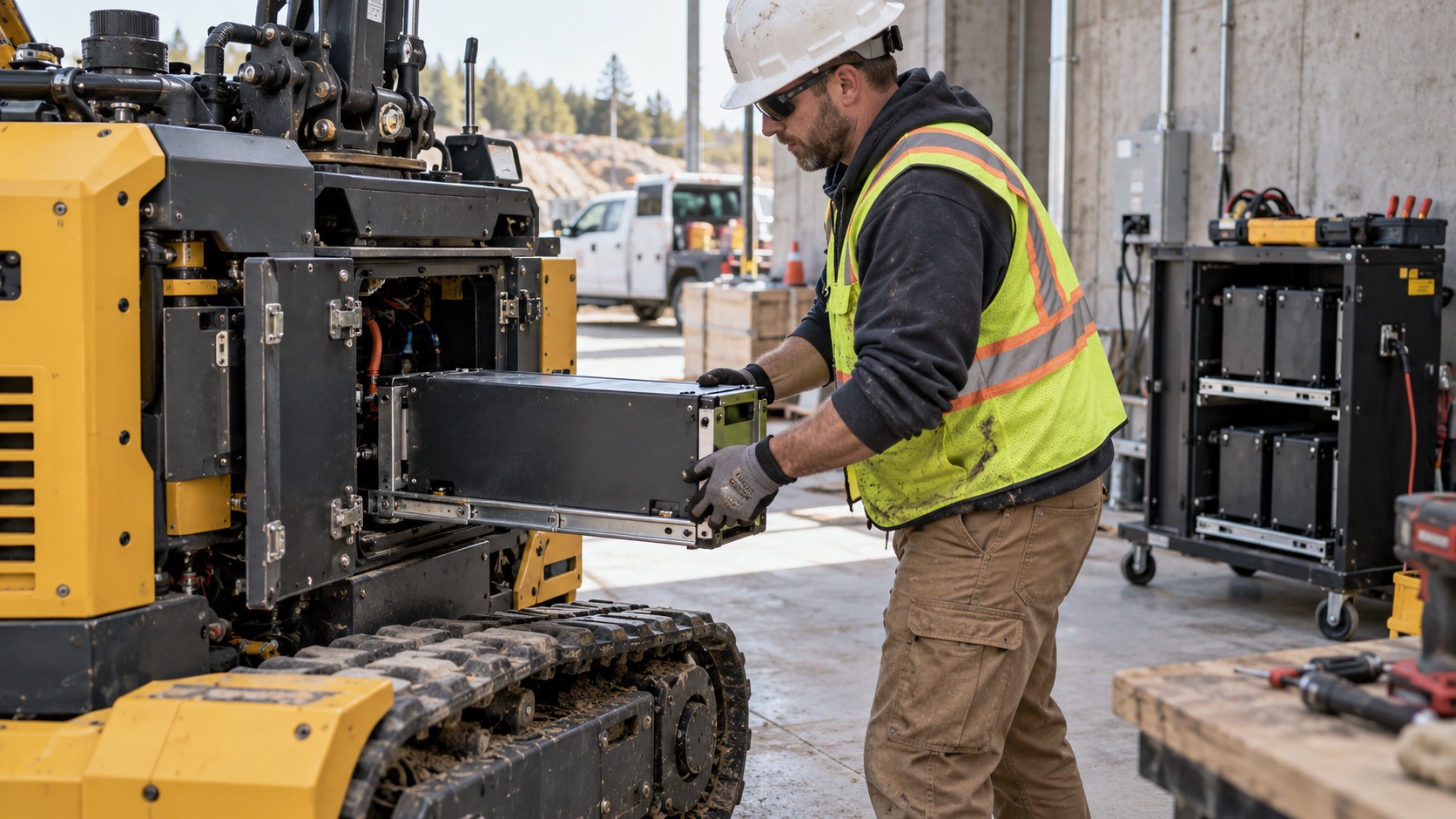
A true hot-swap architecture requires a power path that allows one energy source to be removed while another maintains the required system state. That can be useful when a construction robot is expected to work across long shifts and cannot remain connected to a charger for several hours.
A multi-pack strategy changes the operating equation: one pack or battery set can operate the robot while another charges offline. The All3 Mantis example shows this principle in a heavy-duty construction platform, but the electrical and mechanical details still require careful design.
Mechanical Retention and Connector Sequencing
The pack has to remain locked while the robot experiences vibration, shock, tool movement and uneven terrain. High-current connectors must tolerate repeated insertion cycles and the expected load. If a battery is connected directly to a DC bus with substantial capacitance, pre-charge or another controlled connection method may be required to limit inrush current and contact stress.
Parallel Packs and SOC Difference
Two packs should not simply be connected in parallel without evaluating their voltage and state-of-charge difference. A mismatch can produce unwanted equalization current when the packs connect. The power path may therefore require controlled contactors, isolation, pre-charge circuitry, pack detection, communication, current-sharing logic and defined insertion and removal sequencing.
Pack handling also matters. A battery that is electrically replaceable but too heavy or awkward for a site operator to handle safely may not deliver the intended benefit. Hot swapping makes the most sense when the required uptime justifies the connector, BMS, mechanical and power-path complexity. For lower-duty-cycle machines that naturally stop between tasks, conventional charging may remain simpler.
6. BMS, SOC and Communication with the Robot Controller
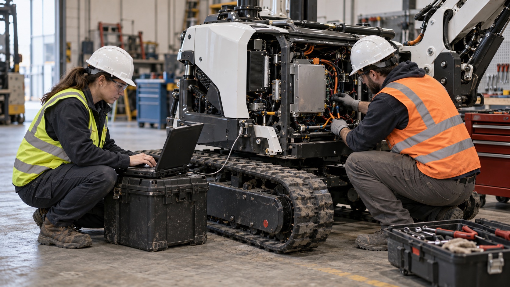
The Smart BMS in a construction robot battery does more than disconnect the battery after a fault. Its data can become part of robot-level control. Relevant measurements and functions may include cell and pack voltage, current, temperature, over-voltage and under-voltage protection, over-current and short-circuit protection, cell balancing, SOC and SOH estimation, fault reporting, charge control, temperature warnings and discharge-current limits.
Consider stair climbing near the end of a shift. The robot controller may need to know not only that the battery reports 20% SOC, but also whether the battery can still support the expected peak current without reaching a protection threshold. A high-temperature warning may allow the controller to reduce tool or traction power before the battery reaches a shutdown condition.
CAN or RS485?
CAN fits naturally into many distributed embedded-control systems and supports robust communication between multiple electronic nodes. RS485 is commonly used as a physical interface for industrial serial networks and can be paired with higher-layer protocols such as Modbus RTU.
Neither interface name by itself defines SOC message format, current scaling, fault codes, message IDs, update frequency, charger commands or timeout behavior. LONGSING’s CAN vs RS485 BMS guide covers these integration differences in greater detail.
For high-speed CAN networks, physical topology and termination affect signal integrity; the conventional implementation uses a line topology with short stubs and termination at both physical ends of the bus. [5]
The OEM should provide the controller interface specification early rather than deciding communication after battery hardware has already been built.
7. Cell Matching, Thermal and Mechanical Integration
As a construction robot battery pack grows, small cell-to-cell differences become harder to ignore.
Cells from the same chemistry and nominal model can still vary in capacity, internal resistance, state of charge and self-discharge behavior. Research on lithium-ion packs identifies these parameters as important forms of pack inconsistency. [3]
Under high current, resistance mismatch is particularly relevant because it changes how current and heat are distributed between parallel cells. That makes battery cell matching increasingly important as the pack gains more series groups, more parallel cells and more demanding peak-power events.
Thermal Behavior Follows the Load Profile
A construction robot does not necessarily create one steady thermal condition. Repeated acceleration, lifting and tool operation can generate alternating high- and low-current periods. Electrical losses increase with current, while enclosure design, cell spacing, cooling interfaces and ambient jobsite temperature determine how quickly that heat leaves the pack.
Pack-level research shows that electrical-current distribution and temperature distribution interact; connection configuration, interconnect resistance and heat-dissipation conditions can influence both current and temperature consistency inside a lithium-ion pack. [4]
The thermal review should therefore consider continuous motor operation, repeated peaks, enclosed battery compartments, high ambient temperature, low-temperature resistance increase, charging after a demanding work cycle and fast or high-rate charging where applicable.
Mechanical Integration Is Part of the Battery Design
Construction equipment may expose the battery to vibration, repeated movement, uneven ground and tool-generated shock. The finished pack may therefore need appropriate cell restraint, module support, connector retention, cable strain relief, enclosure stiffness, insulation, service access and a project-specific dust and environmental protection strategy.
For industrial secondary lithium batteries, IEC 62619:2022 provides safety requirements and tests and lists motive applications such as automated guided vehicles among its examples. The applicable standards for a particular construction robot still depend on the finished machine, target market and equipment classification. [6]
Lithium batteries shipped separately or with equipment also have transport-testing considerations. The UNECE Manual of Tests and Criteria, Revision 8 and Amendment 1 includes lithium cell and battery provisions in subsection 38.3. [7]
8. What an OEM Should Specify Before Designing the Battery Pack
A useful construction robot battery RFQ should describe how the machine actually works. A request for a “48 V high-capacity lithium battery” provides too little information to evaluate loaded voltage, runtime, charging or mechanical integration.
| Parameter | Information to Provide | Why It Matters |
|---|---|---|
| Nominal and maximum voltage | Controller and charger voltage window | Defines series architecture and compatibility |
| Usable energy | Required Wh and operating hours | Drives runtime sizing |
| Continuous current | Sustained traction, arm and tool load | Affects cell, conductor and thermal selection |
| Peak current | Current, duration and repetition | Determines transient power capability |
| Minimum loaded voltage | Controller and BMS threshold | Defines allowable voltage sag |
| Robot mass and payload | Empty, typical and maximum loaded mass | Changes traction and actuator demand |
| Duty cycle and terrain | Standing, driving, climbing, arm and tool periods | Defines real average and peak load |
| Battery envelope | Available L × W × H, mounting and connector location | Influences cell format and layout |
| Weight target | Maximum finished pack mass | Protects payload and mobility targets |
| Temperature | Operating, storage and charging range | Affects energy, power and charging control |
| Charging / hot swap | Charge window, charger interface and swap sequence | Changes pack, connector and fleet design |
| BMS communication | CAN, RS485 or other protocol; message definitions | Defines controller and charger integration |
| Mechanical environment | Vibration, shock, dust and service requirements | Defines enclosure and retention design |
| Lifecycle and market | Usage schedule, service target and sales regions | Supports cell selection and compliance planning |
The most useful early input is a measured or realistically estimated robot load profile. Once voltage range, energy, continuous and peak current, payload, battery space, temperature and charging strategy are known, engineers can compare cell chemistries and pack architectures on the same basis.
A construction robot battery is therefore a coordinated system involving cell selection, series/parallel architecture, BMS logic, communication, thermal design, mechanical integration and charging strategy.
LONGSING supports OEM and ODM rechargeable battery development for robotics and industrial applications. For an application-specific discussion, provide the engineering inputs in the checklist above rather than only a target Ah value.
Frequently Asked Questions About Construction Robot Batteries
Click to explore more information about construction robot battery design
Q: What type of battery is used in construction robots?
A: Rechargeable lithium-ion and LiFePO₄ systems can both be suitable. The choice depends on voltage, usable energy, peak current, pack weight, battery space, duty cycle, charging strategy, temperature and lifecycle targets.
Q: How do you calculate construction robot battery capacity?
A: Estimate or measure average power across a representative duty cycle, multiply by required operating time to obtain usable energy, then account for the usable SOC window, temperature, aging, route variation and operating reserve.
Q: Why does payload reduce robot runtime?
A: Added payload increases the mechanical work needed for acceleration, climbing and many actuator movements. The exact effect depends on terrain and duty cycle because computing, sensing and communication loads may remain almost unchanged.
Q: Why do construction robots need high peak-current capability?
A: Climbing, lifting, motor startup and simultaneous tool operation can produce brief loads far above steady operation. If the pack cannot support them, voltage sag or a BMS current limit may stop the robot even when energy remains.
Q: Is 21700 suitable for a construction robot battery?
A: It can be when the selected cell’s energy, current capability, dimensions and thermal behavior fit the design. A 21700 architecture may reduce physical cell count, but it is not automatically lighter, cooler or longer-lasting than an 18650 design.
Q: Is LiFePO₄ suitable for construction robotics?
A: It can be. LiFePO₄ should be evaluated where its chemistry characteristics and available cell formats match the robot’s mass, volume, voltage, current, charging and lifecycle requirements.
Q: What is a hot-swappable robot battery?
A: It is a battery architecture that allows a pack to be exchanged while another source maintains the required system state. True hot swap requires suitable connectors, locking, power-path control, sequencing, BMS coordination and safe pack handling.
Q: Why does a construction robot need a Smart BMS?
A: The BMS protects cells and monitors voltage, current and temperature, while SOC, SOH, fault and current-limit data can help the controller plan charging, reduce power or stop safely. CAN or RS485 compatibility must include the actual protocol and data definition.
References
[1] All3. All3 unveils next generation All3 Mantis — the heavy-duty quadrupedal robot setting new benchmarks for construction automation. 2026. ↪
[2] Hu, X., Li, S., & Peng, H. A comparative study of equivalent circuit models for Li-ion batteries. Journal of Power Sources, 2012, 198, 359–367. ↪
[3] Zhang, C. et al. Propagation mechanisms and diagnosis of parameter inconsistency within Li-Ion battery packs. Renewable and Sustainable Energy Reviews, 2019, 112, 102–113. ↪
[4] Zhang, R., Wang, K., Ji, Y., & Zhao, G. Study of inconsistencies of cell current and temperature distribution for lithium-ion battery pack. Journal of Energy Storage, 2026, 153, 121080. ↪
[5] Analog Devices. AN-1123: Controller Area Network (CAN) Implementation Guide. ↪
[6] International Electrotechnical Commission. IEC 62619:2022 — Safety requirements for secondary lithium cells and batteries for use in industrial applications. ↪
[7] United Nations Economic Commission for Europe. UN Manual of Tests and Criteria, Revision 8 (2023) and Amendment 1 (2025), subsection 38.3. ↪