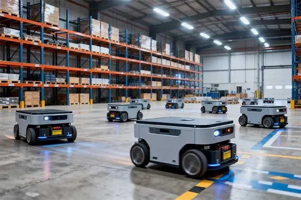
Are your automated machines failing mid-shift? Inconsistent power leads to costly downtime and damaged electrical components. You need a highly stable energy source to keep manufacturing lines running efficiently.
We solve these engineering challenges by designing specialized energy storage architectures that keep your machinery moving.
A reliable robot battery system requires precise matching of cell chemistry, discharge rates, and intelligent management. To design it effectively, engineers must balance capacity requirements with weight limits while ensuring stable power delivery.
Using high-quality lithium-ion cells and configuring an advanced battery management system guarantees continuous operation for automated machinery and mobility devices.
We solve these exact engineering challenges by designing specialized energy storage architectures that keep your machines moving efficiently.
Table of Contents
- Why is the Battery Often the Bottleneck in Robotics?
- How Does a Robot Power System Architecture Work?
- How to Choose the Right Robot Battery?
- What Are the Application-Based Recommendations for Different Robots?
Why is the Battery Often the Bottleneck in Robotics?
The battery is the primary bottleneck in robotics because it must deliver high power bursts while remaining lightweight and compact. Conventional power sources fail to meet the dynamic load demands of rapid acceleration.
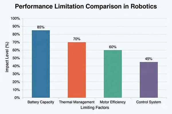
An underperforming robot battery pack reduces operational time and causes system resets under heavy loads.
System Engineering in Energy Constraints
From a system engineering perspective, a robot battery does not operate in isolation. It must seamlessly collaborate with the drive motor, the motherboard computing power, and the motion sensors.
A common mistake in engineering is isolating the battery design from the overall chassis design. While standard power units offer fast deployment, they often fail to handle peak current spikes when a robot lifts heavy payloads while simultaneously calculating complex navigation paths. We must weigh the convenience of standardization against the necessity of customized robot battery packs.
| System Component | Power Draw Characteristics | Operational Impact on Battery |
|---|---|---|
| Drive Motor | High, Dynamic Spikes | Dictates the maximum peak discharge requirements |
| Motherboard Compute | Moderate, Constant | Requires highly stable voltage to avoid system resets |
| Motion Sensors | Low, Sensitive | Highly susceptible to calibration loss during voltage sag |
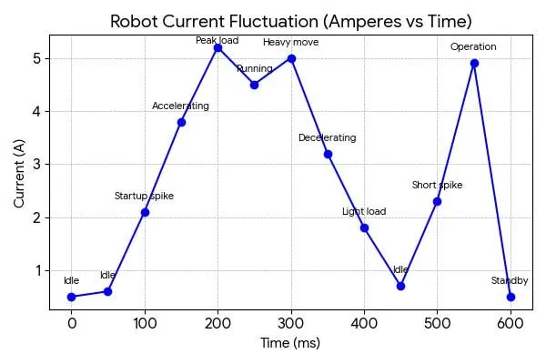
Our Chief Engineer, Jack Song, often emphasizes that high-C discharge lithium cells solve the immediate power draw, but they also require robust thermal dissipation systems. If the motherboard draws 50W constantly and the drive motor suddenly pulls 1000W, a poorly designed robot battery pack will experience severe voltage sag.
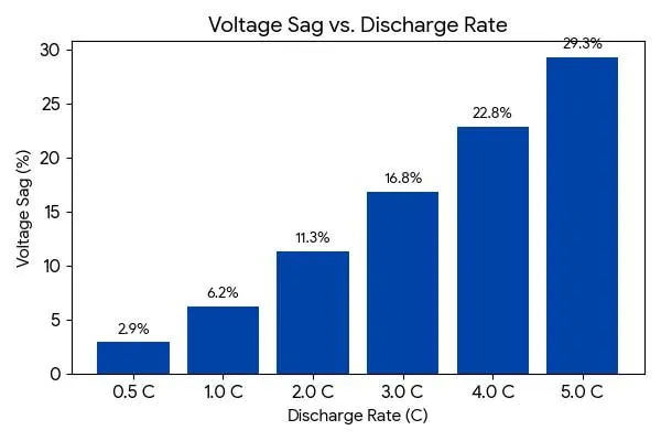
This sudden drop in voltage causes motion sensors to lose calibration and triggers motherboard reboots. Therefore, achieving true system reliability requires analyzing the entire power consumption profile holistically.
Break Your Robot Power Limits
High energy density, stable output.
How Does a Robot Power System Architecture Work?
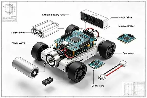
A functional robot power system architecture integrates power cells with protective circuitry and data communication lines(Battery + BMS + MCU + Communication). It regulates voltage outputs, protects against electrical faults, and communicates health data to the main controller.
Efficient architectures utilize a robust robotic battery management system to prevent critical failures during dynamic industrial tasks.
Advanced Communication and Safety Protocols
To achieve operational excellence, a lithium ion battery manufacturer must implement rigorous safety and communication protocols.
We design packs with explosion-proof venting mechanisms[1] and multiple overcurrent protection layers to ensure physical safety. The robot’s main controller must read real-time SOC (State of Charge) and SOH (State of Health) through CANbus/RS485 protocols.
Let me share a recent case where we designed a 12V robot battery for a domestic Chinese robotics factory. The specific application was a compact indoor delivery robot.
We selected INR18650-30Q cells to build a battery pack for robot. The exact specifications included a 12Ah capacity, physical dimensions of 70x80x70mm, and a 30A maximum continuous discharge rate. We designed the 12V (11.1V nominal) voltage system to precisely match their 250W drive motor.
To calculate the current, we divided 250W by 11.1V, which equals a 22.5A continuous current draw. However, during testing, the robot experienced sudden power loss during rapid acceleration. We diagnosed this as BMS false protection because the starting current spiked to 45A.
The BMS for robot batteries cut off the power instantly to protect the circuit. Our solution was adjusting the BMS peak overcurrent delay from 100ms to 500ms and utilizing high-C discharge lithium cells to handle 50A bursts safely inside the robot battery pack.
| System Parameter | Calculation / Protocol | Design Outcome |
|---|---|---|
| Motor Match Current | 250W / 11.1V = 22.5A | Defines the continuous current rating |
| Starting Burst Current | Continuous x 2 (approx 45A) | Requires adjusting BMS delay limits |
| Data Communication | CANbus / RS485 Integration | Provides precise SOC and SOH tracking |
How to Choose the Right Robot Battery?
A robot battery is a lithium-based power cell or pack — NMC, LFP, or Li-Po — selected to match a robot’s peak current draw, operating voltage, runtime capacity, and safety requirements.
Choosing correctly requires analyzing the load profile, nominal voltage rail, watt-hour budget, and chemistry trade-offs before any procurement decision. A mismatched robotics battery causes thermal stress, voltage sag, and premature failure.
Select the Ideal Battery Faster
Engineered for performance and safety.
Step 1: Define Your Load Profile
A load profile maps the current draw of every subsystem — drive motors, onboard computers, and sensors — against time. For a robot battery, the critical values are continuous current (A), peak pulse current (A), peak duration (ms), and duty cycle (%).
Without these four numbers, no engineer can safely rate a battery pack for robot use. Undersizing the continuous rating causes thermal runaway; undersizing the peak rating causes voltage sag[2] that resets microcontrollers mid-task.
| Robot Subsystem | Typical Continuous Draw | Typical Peak Draw | Peak Duration |
|---|---|---|---|
| Drive motors (mobile platform) | 5 – 30 A | 50 – 150 A | 100 – 500 ms |
| Main compute board (edge AI) | 2 – 8 A | 10 – 20 A | 50 – 200 ms |
| Motion sensors (IMU + LiDAR) | 0.5 – 3 A | 3 – 6 A | < 50 ms |
| Manipulator arm (servo-driven) | 3 – 15 A | 30 – 80 A | 200 – 800 ms |
Step 2: Voltage Selection
Robot battery voltage should match the nominal voltage of the drive motor system. A 12V robot battery suits lightweight platforms under 10 kg with brushed DC motors. A 24 V pack covers mid-range mobile robots.
A 48 V or 72 V robotics lithium ion pack is required for heavy-duty platforms, industrial AMRs, and robots with high-torque BLDC or servo motors. Higher voltage reduces cable current, which lowers resistive losses and heat generation across the wiring harness.
Standard Voltage Rails and Their Typical Applications
| Nominal Voltage | Series Cell Count[3] (LFP / NMC) | Typical Platform | Typical Motor Power Range |
|---|---|---|---|
| 12 V | 4S LFP / 3S NMC | Small service robots, UAV ground stations | < 200 W |
| 24 V | 8S LFP / 6S NMC | Delivery robots, inspection drones | 200 – 800 W |
| 48 V | 16S LFP / 13S NMC | AMRs, collaborative robots, exoskeletons | 800 – 3,000 W |
| 72 V | 24S LFP / 20S NMC | Heavy industrial AGVs, legged robots | 3,000 – 10,000 W |
Step 3: Capacity Calculation
Robot battery capacity (measured in watt-hours, Wh) should support the target mission duration with at least a 20 % energy reserve. Calculate required capacity as:
Wh = Average Power Draw (W) × Mission Duration (h) ÷ 0.80
Average power draw must include all subsystems — motors, compute, sensors, and actuators — weighted by their duty cycle. Undersizing capacity causes the robot to reach low-voltage cutoff mid-mission; oversizing adds weight that reduces mobility and payload.
Capacity Sizing Worksheet
| Parameter | Symbol | Example Value | Notes |
|---|---|---|---|
| Drive motor average power | P_motor | 400 W | Measured from load profile, duty-cycle weighted |
| Compute board power | P_compute | 60 W | Includes GPU/edge AI accelerator during active inference |
| Sensor array power | P_sensors | 30 W | LiDAR + IMU + cameras combined |
| Actuator / peripheral power | P_aux | 20 W | Grippers, lights, communication modules |
| Total average power | P_total | 510 W | Sum of above |
| Target mission duration | T | 4 h | Worst-case mission |
| Safety reserve factor | — | ÷ 0.80 | 20 % reserve prevents deep discharge |
| Required pack capacity | Wh_pack | 2,550 Wh | 510 W × 4 h ÷ 0.80 |
Step 4: Battery Chemistry Comparison
NMC (Nickel Manganese Cobalt) offers the highest energy density (200–270 Wh/kg) and suits weight-sensitive robots.
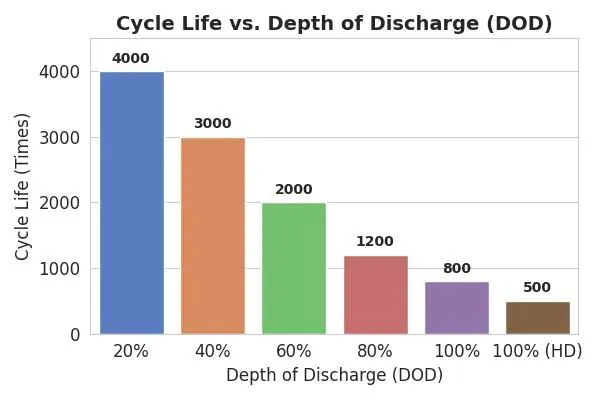
LFP (Lithium Iron Phosphate) provides the safest thermal profile and longest cycle life (2,000–4,000 cycles), making it the standard choice for industrial and infrastructure robots.
Li-Po (Lithium Polymer) delivers the highest peak power and thinnest form factor for UAVs and compact platforms.
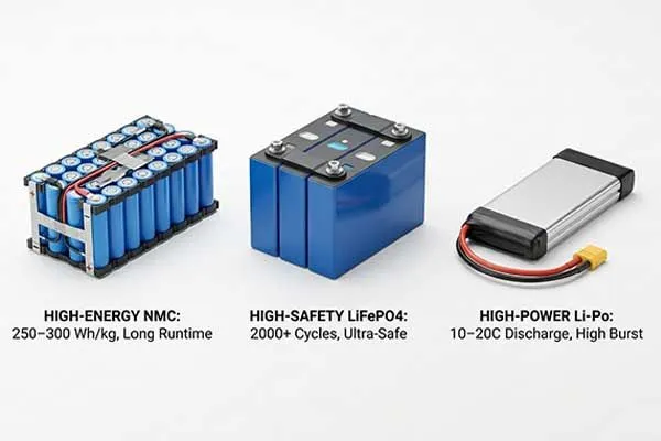
Each chemistry has direct consequences for battery pack for robot mechanical design and BMS specification.
| Property | NMC (Cylindrical / Prismatic) | LFP (Prismatic) | Li-Po (Pouch) |
|---|---|---|---|
| Gravimetric energy density | 200 – 270 Wh/kg | 130 – 180 Wh/kg | 180 – 250 Wh/kg |
| Typical cycle life (80 % DoD) | 800 – 1,500 cycles | 2,000 – 4,000 cycles | 300 – 800 cycles |
| Continuous discharge C-rate | 2C – 5C | 1C – 3C | 5C – 30C |
| Thermal runaway onset temp. | ~170 – 200 °C | ~270 °C | ~130 – 150 °C |
| Operating temperature range | −20 to +55 °C | −20 to +60 °C | −20 to +50 °C |
| Typical robot battery application | AMR, collaborative robot, LEV-derived robot | Industrial AGV, ESS buffer, heavy platform | UAV, racing drone, compact inspection robot |
| BMS complexity | Medium (SOC estimation needs Kalman filter) | High (flat OCV curve makes SOC harder) | Low–Medium |
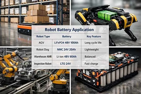
What Are the Application-Based Recommendations for Different Robots?
Different robotic applications require highly specific power solutions. AGVs and AMRs need stable, long-cycle energy. Industrial robotic arms demand continuous stationary power, while UAVs and robot dogs require lightweight, ultra-high discharge capabilities.
Utilizing a custom lithium ion robotics battery ensures that the unique power delivery curve of each specific machine is met accurately.
Matching Power Profiles to Robotic Movement
Robotics applications span across multiple categories, each with distinct motion patterns and power demand profiles: educational robots, mobile robots, AGV, AMR, humanoid robots, industrial robots, warehouse robots, defense robots, military robots, consumer robots, combat robots, battle robots, etc
Let us critically examine the specific energy profiles across various automated platforms. AGV, AMR, and warehouse robots operate in continuous shifts, making LFP chemistry ideal due to its deep cycle endurance.
In strict contrast, a robot dog or UAV demands rapid torque, necessitating high-C discharge lithium cells to prevent altitude loss or balance failure. For a heavy industrial robot or an industrial robotic arm, the focus shifts to robust thermal management within the customized robot battery packs.
| Robot Classification | Key Discharge Requirement | Recommended Battery Solution |
|---|---|---|
| AGV / AMR / Warehouse Robots | Low to Moderate, Continuous | High-capacity LFP chemistry |
| UAV / Robot Dog | Extremely High, Burst Spikes | NMC cells with high-C ratings |
| Industrial Robotic Arm | Moderate, Stable | Grid-tied or heavy NMC pack |
We cannot apply a generic methodology to specialized machines. A robotics lithium ion pack designed for a lightweight drone will degrade rapidly if placed inside an AMR due to completely different thermal accumulation patterns.
Furthermore, a lithium ion battery for robots used in outdoor environments must feature heavy-duty waterproofing and active heating elements. Therefore, designing a battery pack for robot always requires analyzing the specific kinetic movements and resting phases of the target machinery to optimize the internal cell layout and software algorithms.
The right robot battery ensures operational success.
Some emerging concepts such as bio-inspired energy storage systems[4] and environmentally powered robots are redefining how energy is supplied in autonomous machines.
Match Battery to Your Robot Application
Tailored solutions for every scenario.
Conclusion
Designing an industrial robot battery requires a deep understanding of system engineering, dynamic power loads, and advanced communication protocols. By precisely matching the motor requirements, configuring smart BMS safety thresholds, and selecting the correct chemistry, engineers can eliminate critical power bottlenecks.
A dependable robot battery ensures maximum uptime and operational efficiency. Whether you are powering a lightweight drone or a heavy-duty industrial AGV, custom power solutions provide the exact reliability your automated machinery needs to succeed.
Frequently Asked Questions
Click to explore more information about Industrial Robot Battery
Q: What kind of battery is used in robots?
A: Most robots use lithium-based batteries such as lithium-ion (Li-ion) and lithium polymer (LiPo) due to their high energy density, lightweight design, and rechargeability. Industrial robots may also use LiFePO4 or lithium primary batteries for long-life and high-reliability applications.
Q: How long does a robot battery last?
A: Robot battery life depends on usage, load, and battery chemistry. Typically, lithium-ion batteries last 2–5 years or 500–2000 charge cycles, while runtime per charge ranges from 1 to 24 hours depending on the robot’s power consumption.
Q: Which is safer, LiPo or Li-ion?
A: Lithium-ion (Li-ion) batteries are generally safer due to their more stable संरcture and built-in protection systems. LiPo batteries offer higher discharge rates but require stricter handling and battery management systems (BMS) to ensure safety.
Q: Do robots use AC or DC?
A: Most robots operate on DC power because batteries supply direct current. However, industrial robots may convert AC grid power to DC internally for motor drives and control systems.
Q: Do robots run on batteries?
A: Yes, many robots run on batteries, especially mobile robots such as AGVs, AMRs, drones, and service robots. Fixed industrial robots may use wired power but still rely on batteries for backup systems.
Q: How to determine if your robot battery is near end of life?
A: Signs include reduced runtime, longer charging time, voltage drops under load, overheating, and increased internal resistance. Battery management system (BMS) data and cycle count analysis can also indicate degradation.
Q: How to choose the battery for a robot?
A: Key factors include voltage, capacity, discharge rate (C-rate), size, weight, cycle life, and safety requirements. Application-specific needs such as peak current, operating temperature, and duty cycle should also be considered.
Q: What are the top-rated high-capacity batteries for industrial robots?
A: High-capacity options include Li-ion (NMC/NCA), LiFePO4, and advanced lithium primary batteries like Li-SOCl2 for backup power. The best choice depends on whether the priority is energy density, safety, or ultra-long service life.
Reference:
[1]Learn safety features that prevent thermal runaway and contain pressure.↪
[2]Learn what is voltage sag and how it influences the battery.↪
[3]Learn how series can be combined to the designated voltage.↪
[4]Learn next-gen battery systems beyond traditional lithium-ion limitations.↪
Keep Reading:
- Ultimate Robot Dog Battery Supplier Guide: From Prototype to Mass Production
- How to Maximize AMR Robot Battery Uptime: Fast-Charging and Swappable Lithium Battery Systems
- How to Customize AGV Battery Packs for System-Level Integration?
- Humanoid Robot Power Systems: How Can Physical AI Overcome the Energy Bottleneck?