
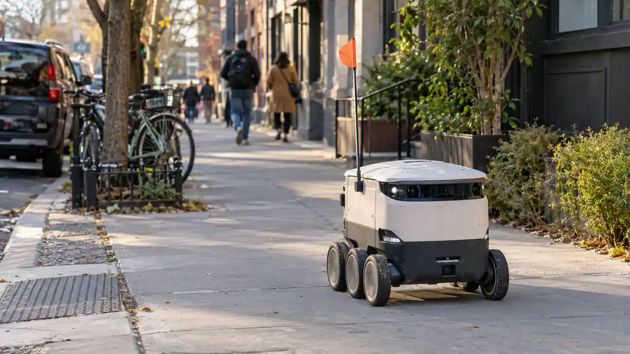
A delivery robot may cruise along a flat sidewalk at a fairly modest load, then encounter a completely different electrical demand a few seconds later. It starts from rest with a full cargo box, climbs a ramp, crosses an uneven curb and accelerates again while its cameras, navigation computer and wireless communication remain powered.
That variation is what makes delivery robot battery design more complicated than choosing a pack from Ah capacity alone.
For a commercial robot, battery sizing has to work across the complete route. There must be enough usable energy to finish the required shift, but also enough current capability to handle short traction peaks without excessive voltage drop. Battery mass matters because every extra kilogram travels with the robot and competes with available payload.
Charging adds another layer. A pack designed for one long overnight charge will not necessarily be optimized in the same way as one that receives several short charges during the day or is replaced between delivery rounds.
The practical design problem is therefore a balance between runtime, payload, battery mass, peak power and fleet availability.
Research on autonomous and sidewalk delivery robots also treats battery capacity, range and charging as operating constraints rather than isolated component specifications. [1][2]
Table of Contents
1. Why Delivery Robot Battery Requirements Change With the Route
A typical autonomous delivery robot has two broad categories of electrical load.
The first is propulsion. Drive motors and motor controllers consume relatively little power while the robot is stationary, but their demand changes quickly with speed, vehicle mass, gradient and rolling resistance.
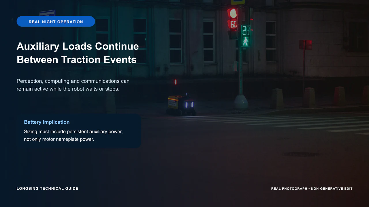
The second category is the electrical load that remains active throughout much of the mission: cameras, LiDAR or radar, GNSS, communication modules, embedded controllers, AI computing hardware, displays and other auxiliary electronics.
This matters because the traction and auxiliary loads behave differently.
A robot waiting for a pedestrian crossing may use almost no traction energy while its perception and computing systems continue running. Minutes later, the same robot may accelerate uphill with a full payload and briefly place a much larger load on the battery.
A useful delivery robot battery test therefore has to reproduce more than steady cruising.
For early prototypes, engineers should collect power or current data during representative parts of the route: normal driving, acceleration, slopes, turns, stops, loaded operation and difficult surface transitions. The resulting duty cycle gives a much better basis for pack sizing than motor nameplate power.
The route itself is part of the delivery robot battery specification.
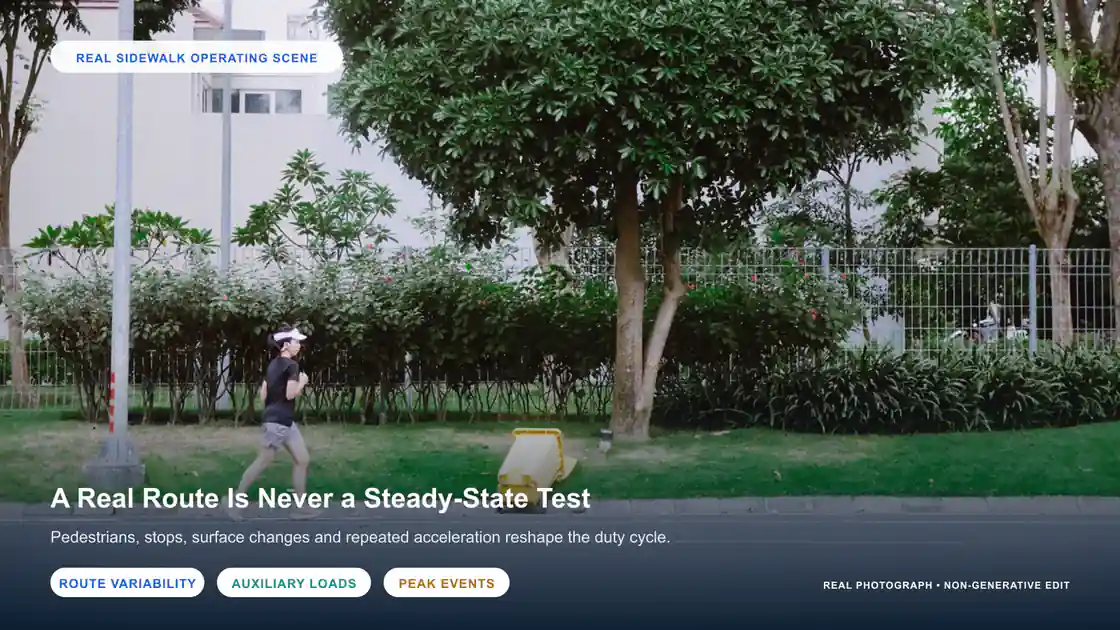
A robot operating mainly on smooth indoor floors can have a very different battery requirement from a machine with the same nominal motor power operating outdoors over ramps, pavement joints and repeated curb transitions.
Payload changes the profile again.
Additional cargo increases the mass the traction system has to move, particularly during acceleration and climbing. At the same time, auxiliary loads such as navigation computers and sensors may remain almost unchanged.
This is why a simple statement such as “a 20% increase in payload causes a 20% reduction in runtime” would be unreliable. The result depends on how much of the total energy is going to traction and how much is being consumed by the rest of the robot.
A related LONGSING technical article on inspection robot battery design covers similar issues around mission profile, current demand and charging for mobile robotics.
2. Sizing a Delivery Robot Battery for Runtime, Payload and Peak Power
Delivery robot battery sizing normally starts with energy.
If measured average electrical power and required operating time are known, engineers can make an initial estimate of usable energy:
Required usable energy ≈ average system power × required operating time
That number is useful, but it should not be treated as the final pack capacity.
The robot still needs operating margin for route variation, temperature, battery aging and the SOC limits used by the system. A delivery fleet may also require some reserve so that robots do not routinely return to the charger at the lowest possible SOC.
Adding Capacity Has a Cost
Increasing pack capacity is an obvious way to extend runtime, but it becomes less attractive when the added battery starts affecting vehicle mass or cargo space.
A heavier pack has to be accelerated and moved up gradients during every route. In a compact sidewalk robot, a larger battery can also occupy volume that would otherwise be available for cargo, suspension movement, electronics or thermal hardware.
At some point, improving the charging schedule may be more useful than continuing to add cells.
That is particularly relevant for fleets that naturally return to a depot several times during the day. If a robot has predictable idle windows, opportunity charging or pack replacement can sometimes increase daily operating availability without requiring the robot to carry enough energy for an entire day in one pack.
A Battery Can Have Enough Wh and Still Be Underspecified
Runtime is only half of the electrical requirement.
Consider a robot that cruises comfortably at moderate current but has to climb a ramp with its maximum payload. The traction system can demand substantially more current for a short period.
Starting from rest, rapid acceleration, tight turning on a high-resistance surface and crossing a curb can create similar events.
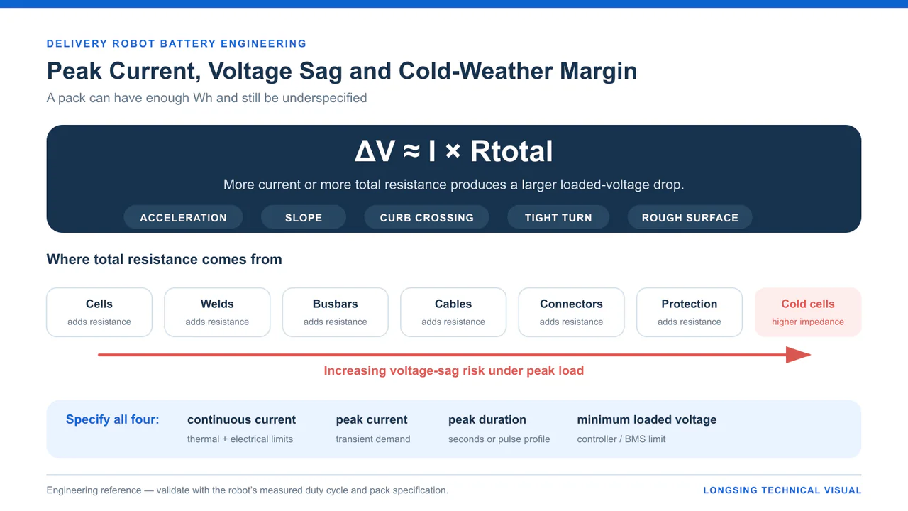
If the delivery robot battery has enough energy but insufficient power capability, the problem often appears as voltage sag.
A simplified relationship is:
Voltage drop increases with current and total electrical resistance.
That resistance is not limited to the electrochemical cells. It also includes busbars, welds, cables, connectors, protection components and other conductive parts of the pack.
As discharge current rises, the loaded pack voltage falls. If the voltage approaches the undervoltage limit of the motor controller or BMS, the robot can stop even though substantial battery capacity remains.
For this reason, a useful delivery robot battery specification should include:
Maximum continuous current, peak current, peak-current duration and minimum acceptable loaded voltage.
Those four values tell a battery engineer far more about a traction application than capacity alone.
Cell Consistency Becomes More Visible Under Load
Multi-cell packs also depend on the consistency of the cells assembled into them.
Small differences in capacity, state of charge or resistance can cause one cell or series group to approach a limit earlier than the others. Under high current, a higher-resistance group may experience a larger voltage drop and trigger an earlier BMS cutoff.
This is one reason battery cell matching remains relevant even when a sophisticated BMS is used.
LONGSING’s existing Cell Matching guide discusses capacity, open-circuit voltage and AC internal resistance as pack-production considerations.
Balancing and cell matching solve different problems. Balancing can manage small SOC differences during use; it does not turn a poorly matched group of cells into an electrically identical pack.
3. 18650, 21700 or LiFePO₄: Which Direction Makes Sense?
This comparison is often framed incorrectly.
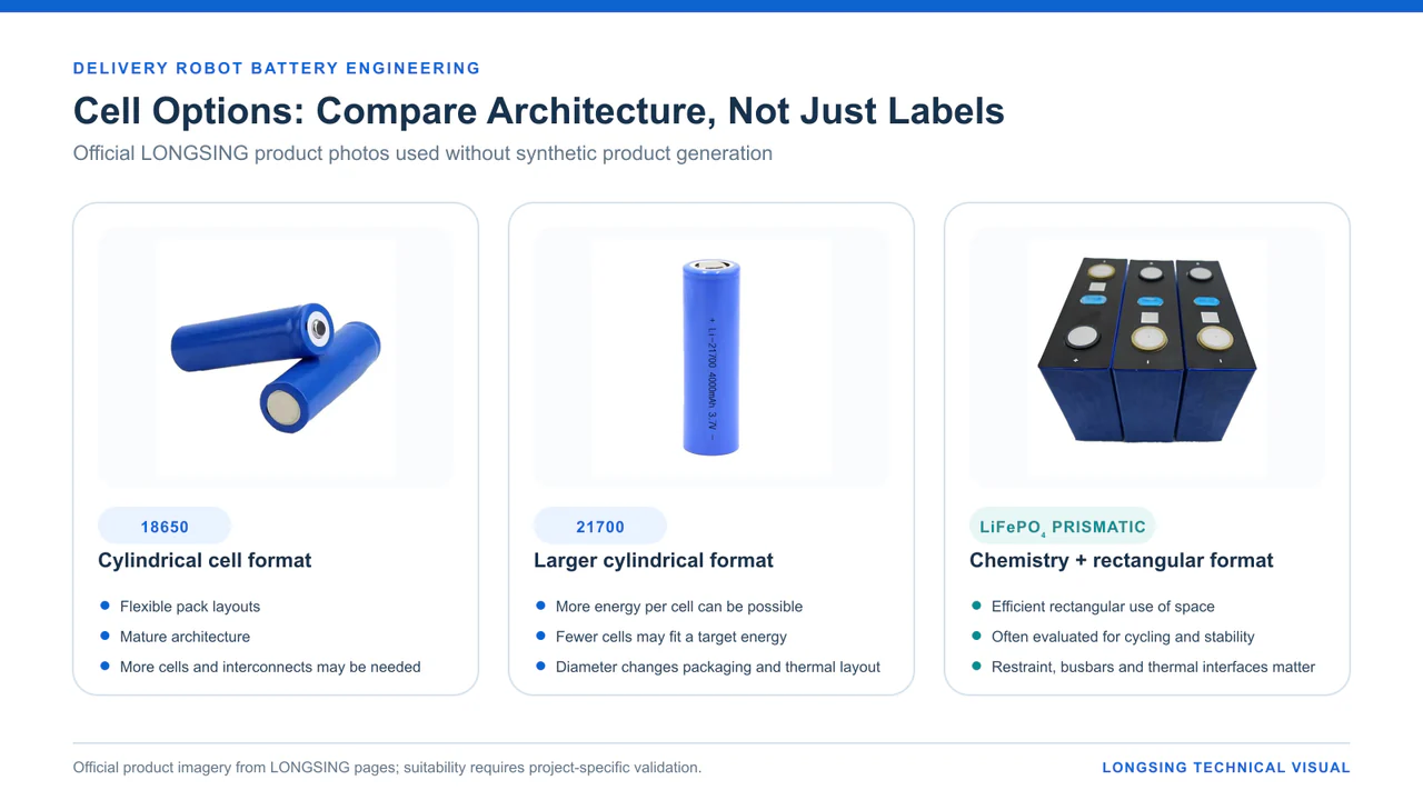
18650 and 21700 are cylindrical cell formats. LiFePO₄ is a cell chemistry.
A LiFePO₄ cell may itself be cylindrical or prismatic. An 18650 or 21700 format can also use different lithium-ion chemistries.
That distinction is important because a robot manufacturer should normally make two related decisions:
Which chemistry fits the energy, power, lifetime and thermal targets?
and
Which cell format fits the pack geometry and manufacturing architecture?
LONGSING’s existing comparison of 18650 vs 21700 vs prismatic cells makes the same format-versus-chemistry distinction and evaluates these options at pack level.
How Common Cell Choices Affect Delivery Robot Pack Design
| Engineering Option | What It Describes | Potential Advantages | Main Design Considerations |
|---|---|---|---|
| 18650 cylindrical cells | Cell format | High layout flexibility; mature cylindrical pack architecture; useful in irregular spaces | Higher physical cell count may increase welds, holders and interconnections |
| 21700 cylindrical cells | Larger cylindrical cell format | More energy can be stored per cell depending on the selected model; fewer physical cells may be possible | Larger diameter changes packaging and thermal layout; performance remains cell-specific |
| LiFePO₄ system | Cell chemistry, available in different formats | Often considered where thermal stability and frequent cycling are major priorities | Pack mass, volume, nominal cell voltage and specific cell format must be evaluated |
| Prismatic architecture | Rectangular cell format | Can use rectangular battery compartments efficiently; can reduce physical cell count | Mechanical restraint, busbars, cell expansion and thermal interfaces require attention |
The table deliberately avoids ranking one option as “best.”
A delivery robot with a narrow, irregular battery compartment may benefit from the layout flexibility of cylindrical cells. Another platform with a large rectangular battery bay may accommodate a prismatic architecture more naturally.
The required service profile matters as well.
If vehicle mass and battery volume are tightly constrained, the project may prioritize energy density. A fleet accumulating frequent cycles may give more weight to long-term cycling behaviour and charging conditions.
These requirements should be discussed before the engineering team commits to a preferred cell type.
18650
An 18650 battery architecture may be worth evaluating where smaller cylindrical cells can make good use of an irregular enclosure or where the project already uses a mature cylindrical-pack production process.
The smaller cell size allows relatively fine adjustment of series and parallel configurations.
Its main system-level trade-off is physical cell count. Reaching a given energy target with more individual cells can mean more holders, weld points and electrical connections.
21700
A 21700 battery architecture retains the cylindrical approach but uses a larger cell.
Depending on the actual cell selected, fewer physical cells may be required to reach a similar energy target. That can change pack structure, parallel count and the number of interconnections.
It should not be assumed that a 21700 pack will automatically be lighter, cooler or longer-lasting. Those outcomes depend on the selected cell, chemistry and complete pack design.
LONGSING currently has both 18650 and 21700 lithium-ion cell categories that can be evaluated for customized series/parallel battery designs.
LiFePO₄
LiFePO₄ deserves separate consideration because the decision is chemical rather than purely geometrical.
For some industrial robot projects, LFP can be attractive where cycling requirements and thermal stability have greater priority. Its pack-level characteristics still depend on the exact cell selected, enclosure, operating SOC range, charging conditions and mechanical structure.
LONGSING also lists 3.2 V LiFePO₄ prismatic cells as one available product direction.
For a compact robot, however, chemistry should not be selected from cycle-life claims alone. The finished pack still has to fit the required volume and mass while delivering the necessary energy and peak power.
4. BMS, SOC, SOH and Communication
A delivery robot BMS is partly a protection system and partly an information source for the vehicle.
Basic protection functions can include monitoring for cell over-voltage, under-voltage, abnormal current and temperature. Depending on system design, the BMS can also control charging and discharging, perform cell balancing and record battery faults.
For a commercial fleet, the data side becomes increasingly important.
SOC Has an Operational Consequence
A rider looking at an e-bike display may only need an approximate battery percentage.
A robot management system may have to decide whether a machine can accept another order.
A 40% SOC reading has little value if the fleet software does not know whether that remaining energy is enough for the assigned route, payload and return trip.
That is why SOC estimation should be considered together with the robot’s energy model rather than treated simply as a dashboard number.
SOH adds a longer-term view.
As a battery ages, usable capacity and electrical behaviour change. Packs of different ages can therefore deliver different practical operating times even if they start a shift showing the same SOC.
SOC and SOH estimation remain active areas of lithium-ion battery-management research, particularly because changing temperature, load and aging complicate accurate estimation. [3]
For fleet maintenance, useful BMS data may include pack voltage, current, temperature, SOC, SOH, charge status and fault information. The exact data set should be defined by the robot controller and maintenance strategy rather than added simply because the BMS supports it.
CAN and RS485 Should Be Chosen at System Level
CAN and RS485 are both used in delivery robot battery systems, but they solve different integration problems.
CAN is common where the battery participates in a distributed embedded control network. RS485 can fit industrial serial communication with controllers, chargers, diagnostic equipment or Modbus-based devices.
The physical interface is only one part of the design.
Engineers still need to define message IDs or addresses, data scaling, update intervals, fault behaviour, timeout logic and communication with the charger.
Selecting “CAN” without agreeing on the actual communication protocol can still leave two pieces of hardware unable to exchange useful data.
LONGSING’s CAN vs RS485 BMS article goes into this integration issue in more detail for AGV, AMR and industrial robot batteries.
5. Charging Strategy, Cold Weather and Fleet Uptime
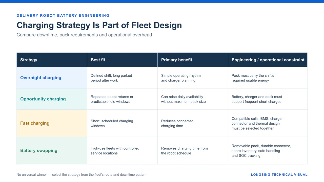
A delivery fleet can increase productive hours in two ways: carry more energy or create more opportunities to recharge that energy.
The second option is sometimes underestimated during early robot development.
One Long Charge or Several Short Ones?
If robots work one defined shift and remain parked overnight, a straightforward overnight charging strategy may be enough.
A fleet running throughout the day has more choices.
A robot may return to a depot between delivery waves, wait several minutes while cargo is loaded, or have predictable periods of low demand. These windows can support opportunity charging if the battery, charger and vehicle architecture are designed for it.
Recent research on sidewalk delivery fleets has even modelled fleet size and spare-battery requirements together, illustrating that battery availability and routing decisions are operationally linked. [2]
Fast charging can reduce downtime further, but the required charge rate needs to be considered during cell selection.
The delivery robot battery, BMS, charger, connector and thermal system all have to support the intended charging profile. Treating fast charging as a requirement added late in development can force significant changes to the pack.
Delivery robot battery swapping takes a different approach. Instead of reducing charging time, it removes charging time from the robot’s operating schedule.
That can work well for some fleets, but it introduces its own engineering requirements: durable connectors, accessible pack mounting, spare-battery inventory, safe handling and reliable SOC tracking between packs.
There is no universal fleet strategy.
For some delivery robots, adding another parallel group may be the simplest route to longer shifts. For another fleet, the same additional battery mass may be less useful than a well-placed charging dock.
Cold Weather Changes Both Runtime and Power
Outdoor robots also have to deal with battery temperature.
At low temperature, lithium-ion cells generally show slower electrochemical kinetics and increased impedance. Usable capacity can fall, while voltage drop under load becomes more noticeable. Low-temperature charging requires particular care because unsuitable conditions can increase lithium-plating risk. [4]
This becomes particularly visible during peak traction loads.
A pack that maintains comfortable voltage margin during a room-temperature test may behave differently after sitting outdoors in winter. A hill climb or loaded acceleration can produce a deeper voltage sag as cell resistance increases.
That is why winter validation should include real load events rather than only checking open-circuit voltage before driving.
Depending on the cell and application, the resulting battery strategy may involve charge-current restrictions, low-temperature charging lockout, thermal insulation, pack heating or a larger operating reserve.
Heating has its own cost: the heater is another electrical load.
For a small autonomous robot, that energy has to come from the same battery that is expected to drive the motors and run the computing system. Thermal management therefore becomes part of the runtime calculation.
6. How to Specify a Delivery Robot Battery Pack
A useful delivery robot battery RFQ should describe how the robot actually works.
“24 V, 20 Ah lithium battery” gives a supplier a nominal voltage and capacity, but very little information about the application.
The following parameters are more useful during early pack development.
1. Voltage and Energy
Provide the required nominal voltage as well as the allowable operating-voltage range.
Usable Wh is generally more informative than Ah alone when engineers are comparing battery architectures.
The energy target should be based on the desired operating shift and measured or estimated robot duty cycle.
2. Continuous and Peak Load
Specify maximum sustained current together with expected peak current and its duration.
A short 80 A pulse and an 80 A load lasting several minutes are completely different battery requirements.
If the motor controller has a defined undervoltage threshold, provide that as well. It gives the battery designer a clear target for acceptable voltage sag.
3. Robot Mass, Payload and Route
Battery suppliers should know the empty vehicle mass, typical cargo mass and maximum payload.
Route information is equally valuable: typical distance, gradients, road or pavement conditions, number of stops and required operating hours.
This helps separate a relatively gentle campus-delivery profile from a more demanding urban route with repeated starts and slopes.
4. Available Battery Envelope
Give the actual mechanical space available for the pack.
Include dimensions, weight limit, mounting points, connector location and cable-exit direction.
This information often influences the cell format before detailed electrical optimisation begins.
5. Environment
Define the expected operating and charging temperatures.
If the robot works outdoors, describe exposure to water, dust, vibration and mechanical shock. Required enclosure or IP targets should come from the vehicle environment rather than being selected as a generic battery feature.
6. Charging
State how the robot is expected to charge:
- overnight charging,
- automated docking,
- opportunity charging,
- fast charging,
- or battery swapping.
Also provide the desired charging window and charger interface.
This is one of the few lists worth keeping because these choices directly change pack architecture.
7. BMS and Host Communication
Define what the robot controller expects from the battery.
At minimum, the engineering team should agree on required protection behaviour and what battery information must be communicated.
If CAN or RS485 is required, also provide the communication specification rather than only the physical interface name.
8. Service-Life Target
“Long cycle life” is too vague for an engineering requirement.
A more useful description is the intended fleet schedule: expected operating days per year, approximate charge/discharge frequency, charging strategy and desired service interval.
That information allows cell selection and operating windows to be evaluated against the real commercial use case.
Delivery Robot Battery Specification Checklist
| Parameter | Information to Provide | Why It Matters |
|---|---|---|
| Nominal voltage | Required DC system voltage | Defines series architecture |
| Operating voltage range | Maximum and minimum accepted by robot | Ensures controller compatibility |
| Usable energy | Required Wh / operating hours | Drives runtime sizing |
| Continuous current | Sustained maximum load | Affects cell and thermal selection |
| Peak current | Current and duration | Determines transient power capability |
| Minimum loaded voltage | Controller/BMS limit | Defines allowable voltage sag |
| Robot weight | Vehicle mass without cargo | Influences traction requirement |
| Payload | Typical and maximum | Changes route energy demand |
| Route profile | Distance, slopes, surface, stop frequency | Defines real-world duty cycle |
| Pack dimensions | Available L × W × H | Influences cell format and layout |
| Weight target | Maximum battery mass | Protects payload and vehicle design |
| Temperature | Operating and charging range | Affects energy, power and charging |
| Charging strategy | Overnight / opportunity / fast / swap | Changes pack and charger requirements |
| Communication | CAN / RS485 / other protocol | Defines BMS integration |
| Environment | Water, dust, vibration, shock | Defines enclosure/mechanical design |
| Service-life target | Fleet usage and charging frequency | Helps evaluate chemistry and cell selection |
| Target market | Countries / regions | Supports compliance planning |
Safety and Transport Requirements
Battery safety requirements should be identified from the final application and target market rather than assumed from robot type alone.
IEC 62619:2022 covers safety requirements and tests for secondary lithium cells and batteries in industrial applications and lists motive applications such as automated guided vehicles among its examples. That makes it relevant background for many industrial mobile-robot projects, although the applicable standard for a specific delivery robot still depends on the finished product and market. [5]
Lithium batteries that are transported also have transport-testing considerations. The current UNECE Manual of Tests and Criteria, Revision 8, together with Amendment 1, includes lithium cell and battery provisions in subsection 38.3. [6]
These requirements are easier to deal with when the destination market and compliance route are discussed early rather than after the mechanical pack design has been frozen.
7. Conclusion
A delivery robot battery has to work with the route, not only with the robot’s nominal electrical specifications.
Average energy determines how long the machine can operate, but the pack also has to survive repeated acceleration, slopes and other short high-current events without excessive voltage drop. Battery mass influences payload and propulsion demand. Temperature changes usable energy and current capability. Charging strategy determines how much energy the robot really needs to carry at one time.
This is why the strongest delivery robot battery specifications tend to come from measured vehicle data.
Once system voltage, route energy, continuous and peak current, payload, temperature, pack space and charging schedule are known, engineers can make a more informed choice between different cell chemistries, formats and series/parallel architectures.
For compact delivery robots, 18650 or 21700 cylindrical cells may be worth evaluating where packaging flexibility and energy-to-weight performance are important. LiFePO₄-based systems can be considered where the project gives more weight to thermal behaviour and frequent cycling. Neither decision should be made independently from the finished pack.
LONGSING supports OEM and ODM rechargeable battery development for robotics and industrial applications, including cell selection, customized pack architecture, BMS integration and communication requirements.
For a new project, the most useful starting information is straightforward: voltage range, required usable energy, continuous and peak current, route profile, payload, temperature, pack dimensions and charging strategy.
Those inputs tell far more about the required battery than Ah capacity by itself.
Frequently Asked Questions About Delivery Robot Batteries
Click to explore more information about delivery robot battery design
Q: What battery chemistry is best for a delivery robot?
A: There is no single chemistry that fits every robot. The selection depends on available space, battery mass, required energy, current demand, charging strategy, operating temperature and expected fleet usage. Energy-oriented lithium-ion designs may suit weight-sensitive robots, while LiFePO₄ can be evaluated where cycling and thermal behaviour receive greater priority.
Q: How should delivery robot battery capacity be calculated?
A: Start with measured or estimated power consumption across the real route and multiply average power by the required operating time to estimate usable energy. Then account for the usable SOC window, temperature, aging, route variation and the operating reserve required by the fleet.
Q: Why does a heavier payload reduce runtime?
A: A heavier robot generally requires more traction energy during acceleration and climbing. The exact effect depends on the route because computing, sensing and communication loads may remain nearly constant even when cargo mass changes.
Q: Why is peak current important if the battery has enough capacity?
A: Capacity describes stored charge or energy; it does not guarantee that the battery can deliver a high transient load without excessive voltage drop. Acceleration, slopes and curb crossings can briefly demand much more current than normal cruising.
Q: Is LiFePO₄ suitable for autonomous delivery robots?
A: It can be. LiFePO₄ is worth evaluating when its chemistry and pack-level characteristics fit the required cycle profile, thermal strategy, mass and volume. It should be compared with other options using the actual robot specification rather than selected from chemistry reputation alone.
Q: What information should a delivery robot BMS provide?
A: The exact data depends on the system, but fleet applications commonly benefit from battery voltage, current, temperature, SOC, SOH, charging status and fault information. Communication behaviour should be agreed with the robot controller and charger during system development.
Q: How does cold weather affect delivery robot batteries?
A: Low temperature can increase lithium-ion cell impedance, reduce usable energy and produce greater voltage sag under load. Charging also needs careful control in cold conditions. Winter testing should therefore include realistic traction loads, not only static battery measurements.
Q: Is fast charging better than battery swapping?
A: They address downtime differently. Fast charging reduces the time connected to a charger but requires compatible cells, thermal management and charging hardware. Swapping keeps the robot moving while another battery charges but requires removable packs, durable connectors and spare-battery management. Fleet operation usually determines which approach is more practical.
References
[1] Vepsäläinen, J. et al. Energy Demand Analysis and Powertrain Design of a High-Speed Delivery Robot Using Synthetic Driving Cycles. Energies, 2022, 15(6), 2198. ↪
[2] Du, Y., Yang, H., Chow, J. Y. J., & Le, T. V. Two-stage stochastic fleet and battery sizing with routing optimization for sidewalk delivery robots. Transportation Research Part E, 2025, 201, 104220. ↪
[3] State of charge and state of health estimation of a lithium-ion battery for electric vehicles: A review. IFAC-PapersOnLine, 2024, 58(13), 460–465. ↪
[4] Tan, S. et al. Review on Low-Temperature Electrolytes for Lithium-Ion and Lithium Metal Batteries. Electrochemical Energy Reviews, 2023, 6, 35. ↪
[5] International Electrotechnical Commission. IEC 62619:2022 — Secondary lithium cells and batteries for use in industrial applications — Safety requirements. ↪
[6] United Nations Economic Commission for Europe. UN Manual of Tests and Criteria, Revision 8 (2023) and Amendment 1 (2025), subsection 38.3. ↪