
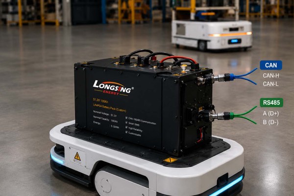
An AGV battery can have the correct voltage, capacity and discharge capability yet still fail system integration if its battery management system cannot exchange the data the host controller expects. Choosing the BMS communication interface too late may lead to firmware changes, connector revisions, additional gateways or another prototype cycle.
For CAN vs RS485 BMS selection, neither interface is universally better. CAN is often a strong fit when the battery participates in a distributed control network, while RS485 is practical for industrial serial communication involving PLCs, chargers, monitoring systems, diagnostic tools or Modbus RTU. The correct choice depends on the host controller, higher-layer protocol, message mapping, communication timing and physical network design.
For AGV, AMR and industrial robot battery systems, engineers should therefore evaluate the communication architecture together with the BMS, charger, controller and wider battery-pack design from the beginning of the project.
Table of Contents
- What Is the Difference Between CAN and RS485 in a Battery BMS?
- How Do CAN and RS485 Compare for AGV and AMR Battery Systems?
- When Should an AGV or Robot Battery Use CAN or RS485?
- What Must Engineers Confirm Before Specifying a Smart BMS Interface?
1.What Is the Difference Between CAN and RS485 in a Battery BMS?
CAN and RS485 can both be used to exchange information between a battery BMS and external equipment, but they are not technically equivalent standards.
CAN defines communication functions beyond electrical signaling, including frame structure, bus arbitration and data-link error handling. RS485, by comparison, primarily defines the electrical characteristics of drivers and receivers for balanced differential communication. [1]
This distinction matters because two devices can use the same physical communication interface and still be unable to understand each other.
For a smart BMS, engineers normally need to define several communication requirements:
- Physical communication interface
- Communication rate
- Higher-layer protocol
- Addressing or message identifiers
- Battery-data definitions
- Transmission timing
- Command behavior
- Warning and fault handling
A connector labelled “CAN” does not automatically make one CAN device compatible with another. The same principle applies to two devices equipped with RS485.
CAN, CANopen and J1939 Are Not the Same Communication Layer
CAN provides the underlying mechanisms used to exchange CAN frames across the network. CAN provides the underlying mechanisms used to exchange CAN frames across the network. An industrial machine may then use a higher-layer communication system such as CANopen, SAE J1939 or a manufacturer-specific CAN protocol. [2]
CAN in Automation describes CANopen as a CAN-based higher-layer communication system that includes communication protocols and device profiles. Battery-specific CANopen device profiles also exist: CiA 418 defines a CANopen interface for battery modules, including communication intended to support interoperability with compatible battery chargers.
SAE J1939 is another higher-layer architecture used in vehicle and machine communication systems. It should not be treated as interchangeable with generic CAN communication.
For a battery project, the statement:
“The controller uses CAN.”
is therefore not a complete communication specification.
The battery engineering team may still need to confirm:
- CAN bitrate
- CANopen, J1939 or proprietary CAN requirements
- Standard or extended identifier format
- Message IDs
- Data-byte definitions
- Scaling and units
- Message transmission intervals
- Fault and warning messages
- Node configuration
- DBC file or equivalent communication documentation
A BMS equipped with CAN hardware does not automatically support CANopen, J1939 or the proprietary CAN message definition required by a particular AGV, AMR or industrial robot controller.
RS485 and Modbus RTU Are Not the Same Thing
RS485 primarily defines the electrical characteristics used for balanced differential serial communication. Modbus, on the other hand, is an application-layer communication protocol that can be implemented over different physical networks. Modbus RTU is commonly deployed over an RS485 serial interface. [3]
Therefore:
RS485 ≠ Modbus RTU
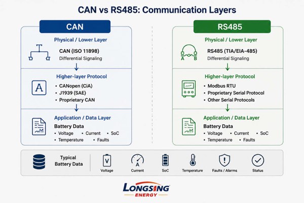
A BMS with RS485 may use:
- Modbus RTU over RS485
- A manufacturer-specific serial protocol
- Another project-defined protocol using an RS485 physical interface
If an AGV controller expects Modbus RTU, simply finding an RS485 port on the BMS is not enough.
The two devices may also need matching:
- Baud rate
- Device address
- Parity
- Stop-bit settings
- Supported functions
- Register map
- Byte order
- Data scaling
- Polling behavior
- Fault definitions
The practical engineering question is therefore not only:
“CAN or RS485?”
It is:
Can the BMS and host controller implement the same communication architecture and correctly interpret the same battery data?
2.How Do CAN and RS485 Compare for AGV and AMR Battery Systems?
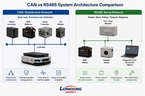
For AGV and AMR batteries, CAN is often well suited to distributed machine-control networks where several intelligent electronic nodes share a bus and message priority must be managed.
RS485 is often a strong option for structured industrial serial communication involving PLCs, chargers, monitoring systems, diagnostic equipment or service tools.
The best BMS communication protocol depends on the complete machine architecture rather than one headline interface specification.
CAN vs RS485 BMS Comparison
| Engineering Factor | CAN | RS485 |
|---|---|---|
| Basic role | CAN-based multi-node communication network | Balanced differential multipoint-capable electrical interface |
| Protocol scope | Includes defined data-link functions such as framing, arbitration and error handling | Primarily defines electrical characteristics; communication behavior depends on the protocol above it |
| Common higher-layer implementations | CANopen, J1939, proprietary CAN | Modbus RTU, proprietary serial protocols |
| Bus access | Non-destructive arbitration is defined by CAN | Determined by the higher-layer protocol and system architecture |
| Message priority | CAN identifier participates in bus arbitration; identifier assignment determines transmission priority | Handled by the selected protocol and application logic |
| Error handling | CAN includes defined data-link error-detection and fault-handling mechanisms | Error detection and recovery depend more heavily on the higher-layer protocol and implementation |
| Typical AGV / robot role | Robot controller, BMS, charger or other distributed control-node communication | PLC, monitoring, diagnostics, configuration, charger or service communication |
| Data-rate / distance relationship | Affected by bitrate, propagation delay, topology, cable and transceiver timing | Affected by baud rate, cable length, topology, termination and transceiver design |
| Main compatibility question | Does the CAN protocol and message definition match the host controller? | Does the serial protocol and register/message definition match the host controller? |
CAN uses a non-destructive arbitration mechanism when more than one node attempts to access the bus. The identifier structure used by the application therefore influences transmission priority. CAN also defines several data-link error-detection mechanisms. These features can be useful in distributed control systems where multiple electronic nodes exchange time-sensitive information. [4]
CAN also defines several data-link error-detection mechanisms. These features can be useful in distributed control systems where multiple electronic nodes exchange time-sensitive information.
Why Maximum Communication Speed Should Not Decide the Interface
Selecting a BMS interface by comparing only headline Mbps figures or maximum cable-distance claims can be misleading.
For RS485, practical performance depends on the relationship between data rate, cable length, cable characteristics, termination, topology and transceiver implementation. Proper termination is also related to the characteristic impedance of the communication cable. [5]
CAN has similar system-level constraints. Practical network performance can be influenced by:
- Bitrate
- Propagation delay
- Bus topology
- Cable characteristics
- Node spacing
- Stub length
- Termination
- Transceiver timing
For an AGV or AMR battery, the more useful engineering questions are:
- How frequently must the controller receive battery data?
- Which messages require higher transmission priority?
- How many network nodes are present?
- Is communication cyclic, event-driven or request/response?
- What should happen if communication is interrupted?
- Does the charger communicate with the BMS?
- Does the charger use the same communication bus?
- What is the actual harness and network topology inside the robot?
What Battery Data May Be Exchanged Through the Smart BMS?
Depending on the selected BMS hardware, firmware and project specification, communicated battery information may include:
- Pack voltage
- Battery current
- State of Charge (SoC)
- Battery temperature
- Operating status
- Warning information
- Protection events
- Charge-current limits
- Discharge-current limits
- Charging permission or control information
The exact parameters, scaling, units, timing and message format depend on the selected BMS and system specification. They should never be assumed solely from the name of the communication interface.
Both CAN and RS485 use differential signaling, but that does not make their electrical implementations interchangeable.
Reliable operation still depends on appropriate cabling, topology, termination, stub length, connector layout, grounding strategy, common-mode conditions, electromagnetic compatibility and isolation where required.
These considerations can be particularly important in AGVs, AMRs and industrial robots because communication harnesses may run near motors, motor drives, contactors, DC/DC converters, chargers and other switching power electronics.
For wider battery-system integration considerations, see LONGSING’s AGV battery pack system integration guide:
3.When Should an AGV or Robot Battery Use CAN or RS485?
An AGV or robot battery should generally use the communication architecture already required by the host machine.
CAN is often appropriate when the robot uses a CAN-based distributed control network and expects the BMS to operate as another intelligent node.
RS485 may be more natural when the controller, PLC, charger or supervisory system already uses a compatible serial protocol.
Existing system compatibility should usually take priority over theoretical interface advantages.
Choose CAN When the Battery Is Part of a Distributed Control Network
CAN is a strong candidate when the smart BMS must exchange information with several intelligent controllers rather than simply respond to a monitoring request.
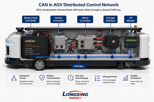
A mobile-robot communication architecture may include:
- Vehicle or robot controller
- Vehicle Control Unit (VCU), where used
- Motor controller
- Battery BMS
- Charger interface
- I/O modules
- Diagnostic controller
CAN arbitration allows multiple nodes to share the network without using a simple first-come communication model.
Depending on the communication specification, battery data may support functions such as:
- Low-SoC return-to-charge decisions
- Battery-status display
- Fault reporting
- Charger coordination
- Charge-current management
- Discharge-current management
- Maintenance diagnostics
However, the BMS and controller still require the same higher-layer communication definition.
A CANopen controller cannot be assumed to communicate correctly with a proprietary CAN BMS merely because both devices use CAN hardware.
Likewise, a J1939-based controller may require completely different application-layer messages from a proprietary robot CAN system.
Choose RS485 When the System Uses Industrial Serial Communication
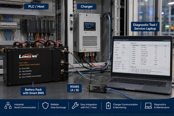
RS485 can be the more natural choice when battery data is exchanged with a PLC, charger, diagnostic device, factory test station or supervisory controller through an established industrial serial architecture.
Typical applications may include:
- Battery-status polling
- Parameter monitoring
- Maintenance diagnostics
- Battery configuration
- Charger communication
- Factory test equipment
- PLC integration
For example, if an existing machine controller already communicates with peripheral devices through Modbus RTU, implementing a compatible RS485 BMS may create a simpler architecture than adding CAN solely for the battery.
The reverse can also be true.
If an AGV already has a CAN network connecting its main control nodes, introducing RS485 only for the battery may require:
- An additional serial interface
- Protocol-conversion software
- A communication gateway
- Additional wiring
- Additional firmware work
- Additional integration testing
This does not make RS485 technically inferior.
It means the communication interface should fit the machine architecture that already exists.
For related application engineering, see LONGSING’s AMR robot battery engineering guide:
And industrial robot battery solutions:
Can a Battery Pack Use Both CAN and RS485?
Yes, provided that the selected BMS hardware and firmware are designed to support both interfaces.
A dual-interface battery architecture may, for example, use:
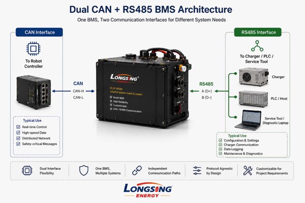
CAN → Main robot controller
RS485 → Charger, PLC, service equipment or diagnostic tool
However, engineers should not assume that both interfaces can operate simultaneously, carry identical data or support every required protocol.
These capabilities depend on the selected BMS hardware, firmware and project design.
Before specifying dual communication, determine:
- Which equipment connects to each interface
- Whether both interfaces must operate concurrently
- Which device has control authority
- Whether charging commands are transmitted
- How communication faults are handled
- Whether duplicated battery data must remain synchronized
- Whether the interfaces require electrical isolation
The goal is not to add as many communication ports as possible.
The goal is to create the simplest communication architecture that satisfies the functional and integration requirements of the robot.
4.What Must Engineers Confirm Before Specifying a Smart BMS Interface?
Before specifying CAN or RS485 for an AGV, AMR or industrial robot battery, engineers should define the complete communication requirement—not only the connector type.
The specification should include:
- Physical interface
- Higher-layer protocol
- Host-controller settings
- Data mapping
- Transmission behavior
- Fault logic
- Charger communication
- Electrical implementation
Define the Communication Protocol Before Battery Development
Communication requirements should ideally be confirmed before the BMS hardware, firmware, connector and wiring architecture are finalized. [6]
If the protocol is defined too late, a custom battery project may require:
- BMS firmware changes
- Connector revisions
- Wiring modifications
- A protocol gateway or converter
- Another prototype cycle
- Additional system validation
For CAN projects, useful information may include:
- CAN bitrate
- Standard or extended identifier requirements
- CANopen, J1939 or proprietary protocol requirements
- Message IDs
- Message cycle times
- Data scaling
- Byte definitions
- Fault and warning definitions
- DBC file or equivalent CAN communication documentation
For RS485 projects, useful information may include:
- Baud rate
- Device address
- Parity
- Stop-bit settings
- Modbus RTU or proprietary protocol definition
- Register map
- Supported commands
- Polling timing
- Byte order
- Data scaling
These parameters determine whether the host controller and battery can correctly interpret each other’s messages.
Smart BMS Integration Checklist
| Requirement | What Should Be Confirmed? | Why It Matters |
| Physical interface | CAN, RS485 or both | Defines the transceiver and wiring architecture |
| Higher-layer protocol | CANopen, J1939, Modbus RTU, proprietary protocol, etc. | Both devices require compatible communication rules |
| Host controller | Robot controller, VCU, PLC or charger model | Establishes the existing machine architecture |
| Communication rate | CAN bitrate or RS485 baud rate | Both ends require compatible communication settings |
| Addressing | CAN IDs, CANopen node ID, Modbus address or project-defined addressing | Allows devices and messages to be identified correctly |
| Message definition | CAN message map, object dictionary, register map or proprietary commands | Defines the meaning of transmitted data |
| Required BMS data | Voltage, current, SoC, temperature, status, faults and limits | Determines which battery information the controller requires |
| Update behavior | Cyclic, event-driven or request/response | Affects response time and network loading |
| Fault handling | Warning, protection, shutdown and communication-loss logic | Defines how the robot responds to abnormal conditions |
| Charger interface | Protocol, current/voltage limits, permission commands and charging-state data | Supports coordinated charging where required |
| Electrical design | Termination, isolation, grounding, topology and EMC considerations | Supports reliable communication in the actual machine environment |
| Connector and pinout | CAN-H/CAN-L, RS485 A/B, ground/reference and auxiliary signals | Prevents physical wiring mismatch |
A Stronger RFQ Requires More Than “48 V AGV Battery with CAN”
A useful battery RFQ contains much more than:
“48 V AGV battery with CAN.”
A stronger engineering specification should include:
Battery voltage and capacity + continuous/peak current + host controller + communication interface + higher-layer protocol + message definition + charger interface + connector/pinout + mechanical constraints + operating environment.
For proprietary CAN systems, providing a DBC file or equivalent CAN message definition during the RFQ stage can reduce ambiguity.
For Modbus RTU systems, the equivalent input is normally a clearly defined register map and serial communication configuration.
Why Custom Battery Pack Communication Design Matters
BMS communication is not an isolated software feature.
It can affect the wider custom battery-pack architecture, including:
- BMS hardware selection
- Firmware development
- Connector design
- Wiring harnesses
- Charger compatibility
- Diagnostics
- Final system validation
For this reason, a custom lithium battery pack for an AGV or AMR should be evaluated as a complete system rather than as cells plus a generic BMS.
Voltage, capacity and discharge current still matter, but the battery also has to communicate correctly with the robot controller and charging architecture.
Communication should therefore be validated inside the actual robot system rather than only by confirming that CAN frames or RS485 data appear on a development tool.
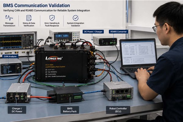
Depending on project requirements, validation may include:
- BMS and controller startup
- Normal charge and discharge states
- Low-SoC behavior
- Temperature warnings
- Protection events
- Charger connection and disconnection
- Communication loss
- Power cycling
- Recovery after bus interruption
- Simultaneous network traffic
For a custom AGV, AMR or industrial robot battery project, providing these communication requirements at the beginning allows the BMS interface, firmware and wiring architecture to be evaluated together with the wider battery system.
LONGSING supports custom lithium-ion battery pack solutions in which voltage, capacity, pack structure, BMS functions and communication requirements can be evaluated according to the target application and system-integration requirements:https://www.longsingtech.com/product-category/battery-packs/
Conclusion
There is no universal winner in CAN vs RS485 BMS selection.
CAN often fits distributed AGV and robot control networks, while RS485 remains practical for PLC, charger, monitoring and industrial serial communication.
The decisive factor is compatibility: interface, protocol, data mapping, timing, wiring, charger behavior and fault logic must match the host system.
Define these requirements before finalizing the battery and BMS architecture.
Frequently Asked Questions
Click to explore more information about CAN vs RS485 BMS communication
Q: Is CAN better than RS485 for a BMS?
A: Not universally. CAN is often well suited to distributed control networks because it includes arbitration and defined data-link error-handling mechanisms. RS485 is widely used for industrial serial communication and can be effective for PLC integration, monitoring, diagnostics and charger communication. The better choice depends on the host controller, required protocol and overall system architecture.
Q: Which BMS communication interface is better for an AGV?
A: CAN is often appropriate when the AGV already uses a CAN-based control network. RS485 may be more suitable when the controller, PLC or charger communicates through Modbus RTU or another compatible serial protocol. Existing controller compatibility should normally guide the interface selection.
Q: Is CANopen the same as CAN bus?
A: No. CAN provides the underlying network and data-link mechanisms, while CANopen is a higher-layer communication system built on CAN. A BMS with a CAN interface does not automatically support CANopen unless the required CANopen communication functions and device profiles are implemented.
Q: Is J1939 the same as CAN?
A: No. SAE J1939 is a higher-layer communication architecture that operates over CAN-based networks. Two devices with CAN hardware are not automatically J1939-compatible. The required message definitions, parameters and network behavior must also be implemented.
Q: Is Modbus RTU the same as RS485?
A: No. RS485 primarily defines the electrical characteristics of the serial interface, while Modbus RTU is a communication protocol commonly implemented over RS485. A BMS can also use a proprietary serial protocol over an RS485 interface.
Q: What battery data can a smart BMS send to an AGV controller?
A: Depending on the BMS design and project specification, communicated information may include pack voltage, current, State of Charge, battery temperatures, operating status, warnings, protection events and charge or discharge limits. The exact data fields, scaling and transmission behavior should be confirmed during system integration.
Q: Can a CAN BMS communicate with any CAN controller?
A: No. Having CAN hardware on both devices does not guarantee compatibility. CAN bitrate, identifier format, message IDs, data encoding, transmission intervals and the higher-layer communication protocol must also match the requirements of the AGV, AMR or industrial robot controller.
Q: What information should I provide for CAN or RS485 BMS integration?
A: Useful information includes the controller and charger models, required communication interface, higher-layer protocol, communication rate, message or register map, required battery parameters, connector pinout, addressing requirements and fault-handling logic. For proprietary CAN systems, a DBC file or equivalent message definition can also help reduce integration ambiguity.
Reference:
[1]Understand the fundamental technical difference between CAN and RS485 in BMS communication.↪
[2]Understand why CAN, CANopen and J1939 should not be treated as the same communication layer.↪