
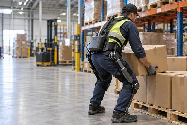
A mobile robot can carry a larger battery without placing that mass directly on a person. A powered exoskeleton cannot.
Every additional watt-hour may extend operating time, but it also adds battery volume and mass to a system that is worn and moved with the user. Reduce the battery too aggressively, however, and the exoskeleton may lose runtime, voltage margin or peak actuator capability.
That makes the exoskeleton battery both an electrical and mechanical design problem.
The central trade-off is:
RUNTIME ↔ WEIGHT ↔ PEAK POWER
Current industrial exoskeletons also show why charging workflow matters. Replaceable and hot-swappable battery architectures are already being used in some powered industrial systems to reduce downtime during long operating periods. [3] [4]
Featured Snippet: What Battery Is Suitable for a Powered Exoskeleton?
Rechargeable lithium-ion battery packs are often suitable for powered exoskeletons because they can combine useful energy storage with the power capability required by electric actuators. However, there is no universal exoskeleton battery. Cell chemistry, format, voltage and capacity should be selected from actuator loads, duty cycle, runtime target, allowable battery mass, installation space, charging strategy, thermal conditions and safety requirements.
1. Why Powered Exoskeletons Create a Unique Battery Design Problem
A powered exoskeleton carries its energy source on or close to the wearer. Battery mass therefore affects more than runtime: it can influence system mass distribution, movement, mechanical layout and the energy required to move the complete wearable system.
That is what makes the battery problem different from many floor-based robots.
Passive exoskeletons may store or redirect mechanical energy without relying on an onboard traction battery. This article focuses specifically on powered exoskeletons, where actuators, controllers and sensors require an onboard rechargeable power source.
Battery Mass Is Wearable Mass
For an AMR or other floor-based robot, adding battery capacity increases vehicle mass.
For an exoskeleton, that additional mass moves with the wearer.
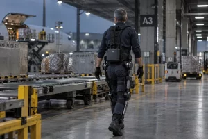
Wearable-robotics research therefore considers not only total system mass, but also where that mass is positioned. One lightweight ankle-exoskeleton design placed a large proportion of the system mass near the waist, reducing the amount of hardware carried farther down the limbs. [2]
This gives battery engineers three closely related questions:
- How much battery mass can the system accept?
- Where can that mass be located?
- How does its position affect the complete wearable structure?
A battery mounted near the waist and a battery of the same mass mounted farther along a limb create different mechanical design problems.
More Energy Can Extend Runtime—but Also Changes the System
The basic battery-energy relationship is:
Nominal Energy (Wh) = Nominal Voltage (V) × Capacity (Ah)
Increasing Wh can provide more potential operating time.
It can also require:
- More cells
- Larger pack volume
- Higher pack mass
- Stronger mounting structures
- Different weight distribution
- Additional mechanical protection
- Longer charging time at the same charging power
For wearable robotics, this creates an important system-level trade-off.
More battery energy improves the available energy reserve, but the additional pack mass becomes part of the system that must move with the user.
Specific energy—Wh per unit mass—is therefore important, but it is only one selection parameter. Robotics battery research also identifies factors such as specific power, current variation, lifetime, temperature behavior and safety as relevant when choosing a battery technology. [1]
The design target should not be:
the largest battery that can fit
but:
enough usable energy to meet the operating requirement within the allowable wearable mass and geometry.
Actuator Peak Power Is a Separate Requirement
Energy and power are related, but they solve different design problems.
Usable energy in Wh mainly determines how long the system can operate.
Continuous power determines what sustained electrical load the pack can support.
Peak power determines whether the battery can support short, demanding actuator events without excessive voltage drop.
Depending on the exoskeleton architecture, high-load events may include:
- Starting a lift
- Standing from a lower position
- Rapid joint movement
- Acceleration
- Stair or incline assistance
- High-torque load assistance
- Multiple actuators operating simultaneously
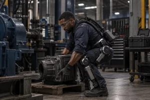
Wearable robots can experience substantial variation between average and peak power demand. [1]
A pack may therefore contain enough total energy for the required operating period but still be unsuitable if:
- Battery voltage sags excessively
- BMS overcurrent protection activates
- Connector losses become too large
- Interconnects cannot support the transient load
- Cell or pack temperature exceeds the defined limit
OEMs should provide both the energy requirement and the actuator power waveform.
Duty Cycle Matters More Than Motor Nameplate Power
Battery sizing should not be based only on:
Motor power × required hours
An exoskeleton rarely operates every actuator continuously at rated power.
Actual energy consumption depends on factors such as:
- Active-assistance time
- Walking pattern
- Lifting frequency
- Idle periods
- Joint torque and speed
- Payload
- Terrain or incline
- Number of active joints
- Control strategy
- Regenerative operation where applicable
Published exoskeleton research has used average task power for energy sizing while separately checking worst-case peak-power requirements.
A useful first-order model is:
Erequired = Σ(Pmode × tmode)
where each significant operating mode is represented by its actual power and duration.
If regenerative operation is used, recovered energy should only be included after the real regeneration profile and battery charge-acceptance behavior have been measured and validated.
2. How Should a Battery Pack for Wearable Robotics Be Designed?
A battery pack for wearable robotics should be designed from the complete system requirement.
Usable energy, actuator peak power, battery mass, cell format, pack placement, BMS, SOC estimation, thermal behavior, mechanical durability and charging workflow all interact.
Size Usable Energy From the Operating Profile
A first-order runtime relationship is:
Estimated Runtime ≈ Usable Battery Energy ÷ Average System Power
The important term is usable battery energy.
Nominal pack energy is not necessarily equal to the energy available to the exoskeleton.
Usable energy can be influenced by:
- Minimum controller voltage
- Motor-drive voltage requirements
- Cell discharge characteristics
- Voltage sag under load
- BMS cutoff
- Conversion losses
- Temperature
- Battery aging
- Required reserve
For an exoskeleton with multiple operating states, the OEM should provide a representative duty cycle rather than only a single average-current estimate.
That profile may include:
walking / assistance
- lifting events
- standing / idle
- high-torque events
- controller and sensor loads
The resulting energy budget determines the required Wh.
Peak-current capability should then be evaluated separately.
Check Peak Power and Loaded Voltage
A useful first-order relationship is:
Vload ≈ VOC − I × Rtotal
Rtotal includes more than cell internal resistance.
The complete current path may include:
Cells → Interconnections → BMS → Switching Devices → Cable → Connector → Motor Controller
At high actuator current, voltage losses across these components can become significant.
The OEM should therefore define:
- Peak current
- Peak duration
- Peak repetition frequency
- Number of actuators active simultaneously
- Minimum acceptable system voltage
- Recovery time between events
This is also why a larger-capacity cell is not automatically a better exoskeleton cell.
The pack must answer two separate questions:
How much energy must the system carry?
and:
How quickly must that energy be delivered?
Choose Cell Chemistry and Format at Pack Level
18650, 21700, pouch/polymer and LiFePO₄ architectures can all be technically relevant depending on the exoskeleton.
There is no universal best option.
The useful comparison is:
Which architecture provides the required energy, power, mass, geometry, lifecycle and thermal behavior in the completed battery pack?
18650 Lithium-Ion Cells
LONGSING’s 18650 battery product direction provides a smaller standardized cylindrical format that can be configured into different series and parallel arrangements.
For an exoskeleton pack, smaller individual cells can provide useful layout flexibility.
The trade-off is that reaching a given energy target may require more physical cells and interconnections.
21700 Lithium-Ion Cells
A 21700 battery uses a larger cylindrical format.
Depending on the selected cell, this may allow a design to achieve its energy requirement with fewer physical cells.
That does not automatically mean:
- Lower pack mass
- Simpler thermal design
- Better cycle life
- Lower BMS complexity
- Better wearable integration
The selected cell model, discharge requirement and complete pack architecture still determine the result.
For a deeper format-level comparison, LONGSING’s existing 18650 vs 21700 vs Prismatic Cells article can be used as supporting reading.
Pouch / Polymer Lithium Cells
Pouch cells can be relevant where the available battery compartment favors a flatter or non-cylindrical layout.
Their mechanical flexibility can be useful, but the pack still needs appropriate mechanical protection, thermal design and allowance for dimensional change during service.
Power capability also needs to be confirmed for the selected cell rather than assumed from the pouch format itself.
LiFePO₄
LiFePO₄ may be worth evaluating when cycle-life, power or system-safety priorities carry more weight than minimizing battery mass and volume.
However, chemistry selection remains a multi-criteria engineering decision.
Specific energy, specific power, temperature behavior, lifecycle, charging and the mechanical battery envelope all need to be considered together. [1]
Battery Placement Is Part of Mechanical Design
Battery location should be decided together with the mechanical architecture.
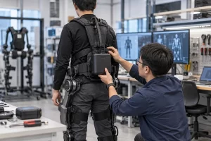
Possible locations may include:
- Waist
- Back
- Hip
- Limb-mounted modules
- Distributed battery modules
Each option affects:
- Center of gravity
- Weight distribution
- Cable length
- Voltage drop
- Harness routing
- Connector position
- Impact protection
- Heat dissipation
- Accessibility for replacement
Placing the pack closer to the torso may reduce distal mass, but it may compete with controllers, actuators or structural components.
A distributed architecture may improve balance but requires additional wiring and connectors.
There is no universally best mounting location.
The appropriate position depends on the complete exoskeleton.
Hot-Swappable and Replaceable Batteries Can Change the Runtime Strategy
A single large fixed battery is not the only way to achieve long operating availability.
Some industrial powered exoskeletons already use replaceable or hot-swappable battery architectures. Ottobock has demonstrated an easily replaceable battery concept in a powered industrial exoskeleton, while German Bionic publicly describes hot-swappable batteries in its industrial platform. [3] [4]
This creates two different design strategies:
One large fixed pack
versus
Smaller replaceable packs + charged spares
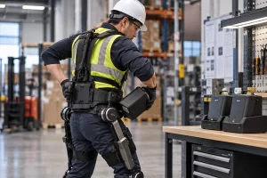
A replaceable architecture can reduce charging downtime and support longer work periods.
It also adds new engineering requirements:
- Connector cycle life
- Mechanical latching
- Safe electrical disconnection
- Pack detection
- Pack identification where required
- Spare-pack management
- Charging logistics
- Environmental protection at the interface
Hot swapping is therefore an operational system architecture—not just a connector choice.
Not every exoskeleton requires it.
The Smart BMS Should Reflect the Exoskeleton System
Relevant BMS functions may include:
- Overcharge protection
- Overdischarge protection
- Overcurrent protection
- Short-circuit protection
- Cell-voltage monitoring
- Temperature monitoring
- Cell balancing
- SOC estimation
- Fault reporting
- SOH monitoring where needed
- Charge and discharge limits
The BMS should be coordinated with:
Battery Pack ↔ Exoskeleton Controller ↔ Motor Drives ↔ Charger
Protection thresholds should not be selected independently from the actuator system.
For example, if normal actuator transients approach the BMS overcurrent threshold, the system may experience unnecessary shutdowns even though the battery cells remain within acceptable conditions.
SOC Accuracy Matters for Operational Availability
Powered exoskeletons also need useful information about how much energy remains.
Battery voltage alone may not provide sufficiently accurate SOC information across different loads, temperatures and aging states.
Fuel-gauge systems can combine current integration, voltage information and battery models to improve estimation. [5]
Incorrect SOC estimation creates two different problems.
SOC overestimated:
The system may lose assistance earlier than expected.
SOC underestimated:
Usable battery energy may remain unnecessarily reserved.
OEMs should therefore define:
- Required SOC resolution
- Low-energy warning behavior
- Shutdown reserve
- Remaining-runtime requirement
- Pack-replacement behavior
- SOH requirement where applicable
Battery Communication Should Follow the Controller Architecture
Possible communication interfaces may include:
- CAN
- UART
- SMBus
- RS485 in some industrial architectures
- Proprietary communication
No single interface is required for every exoskeleton.
The controller architecture should determine what is needed.
Projects may also need to specify:
- Bitrate
- Message IDs
- Data map
- SOC reporting
- Fault messages
- Charge and discharge limits
- Charger communication
- Communication-loss behavior
LONGSING’s existing CAN vs RS485 BMS article provides a deeper protocol comparison without repeating that subject here.
Thermal Design Must Cover Operation and Charging
Battery heat can come from:
- Cell internal resistance
- Repeated actuator-current peaks
- Sustained high load
- BMS switching devices
- Nearby power electronics
- Charging
The complete pack should therefore be validated against:
- Ambient temperature
- Actual wearable location
- Enclosure design
- Actuator duty cycle
- Peak-load events
- Charging conditions
- Available heat-dissipation paths
The important question is not simply:
What is the cell’s datasheet temperature range?
It is:
What temperature does the battery reach inside the operating exoskeleton?
Charging temperature should also be considered separately from discharge temperature.
Wearable Packs Need Mechanical Durability
An exoskeleton battery experiences repeated mechanical movement that many stationary battery systems do not.
Pack design may need to consider:
- Repeated body movement
- Vibration
- Shock
- Accidental impact
- Connector wear
- Cable flexing
- Strain relief
- Pack retention
- Enclosure strength
- Removal and reinsertion cycles
A battery that works correctly during bench testing still needs validation in the real wearable mechanical environment.
Multi-Cell Packs Depend on Cell Consistency
Series and parallel packs also depend on individual-cell consistency.
Important production parameters can include:
- Capacity
- Open-circuit voltage
- Internal resistance / ACIR
A weaker cell or parallel group can limit usable pack capacity or reach a BMS threshold earlier than neighboring groups.
LONGSING’s dedicated Battery Cell Matching article covers capacity, OCV and ACIR matching in greater detail.
3. How Do Battery Priorities Change Across Exoskeleton Applications?
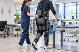
Different powered exoskeletons can require very different battery strategies.
Actuator architecture, operating environment, duty cycle and required uptime should define the battery rather than assuming one standard wearable-robot pack.
Exoskeleton Battery Application Comparison
| Application | Main Load Characteristic | Battery Priority | Weight Sensitivity | Charging / Swapping Strategy | Important Design Consideration |
|---|---|---|---|---|---|
| Industrial Lifting-Assist Exoskeleton | Intermittent high-torque assistance during lifting and movement | Peak power + operational availability | High | Replaceable or swappable packs may support long shifts | Repeated peak loads, rugged mounting and quick replacement |
| Logistics / Warehouse Exoskeleton | Frequent movement with repeated assistance events | Runtime + low wearable mass | High | Spare-pack rotation may reduce downtime | Duty-cycle variability and connector durability |
| Rehabilitation Exoskeleton | Controlled repeated movement under defined session profiles | Predictable energy delivery + monitoring | Medium to high | Plug-in or off-device charging may fit scheduled sessions | Accurate SOC, defined operating cycle and documentation requirements |
| Mobility-Assist Exoskeleton | Repeated walking, standing and transition events | Energy + power + low carried mass | Very high | Architecture depends on intended mobility duration | Battery placement, reserve energy and reliable SOC |
| Field / Rescue Exoskeleton | Highly variable movement, terrain and load assistance | Peak power + robustness + operational availability | High | Replaceable packs may help where charging access is limited | Mechanical protection, environment and spare-pack logistics |
These are engineering tendencies rather than fixed specifications.
An actual powered exoskeleton may combine characteristics from several categories.
4. What Should OEMs Specify Before Developing a Custom Exoskeleton Battery?
A useful custom exoskeleton battery RFQ should describe the complete system rather than begin with a preferred cell format.
For example:
“We need a 21700 exoskeleton battery.”
does not provide enough information to determine whether 21700 is actually appropriate.
Electrical Requirements
Provide:
- Nominal system voltage
- Maximum battery voltage
- Minimum operating voltage
- Average system power
- Continuous current
- Actuator peak current
- Peak duration
- Peak repetition rate
- Number of actuators operating simultaneously
- Required runtime
- End-of-operation reserve
Where possible, provide a real:
Current-versus-time or power-versus-time waveform
from the prototype or a representative movement cycle.
Duty-Cycle Requirements
Define:
- Walking duration
- Lifting frequency
- Standing and idle periods
- Typical assistance level
- Worst-case assistance level
- Expected payload
- Terrain or incline
- Number of active joints
- Regenerative behavior where applicable
- Session or shift duration
These parameters allow the mechanical task to be converted into a realistic energy requirement.
Mechanical Requirements
Provide:
- Maximum battery dimensions
- Maximum acceptable pack mass
- Installation location
- Center-of-gravity constraints
- Left/right balance where applicable
- Mounting orientation
- Pack-retention method
- Connector location
- Cable routing
- Shock and vibration requirements
- Impact requirements
- Available cooling or heat-dissipation path
Battery placement should be finalized together with the exoskeleton’s mechanical structure.
Fixed, Removable or Swappable Architecture
Specify whether the battery is:
- Fixed
- Service replaceable
- Designed for quick replacement
- Hot-swappable at system level
Also define:
- Required exchange time
- Whether system power must remain available during replacement
- Spare-pack workflow
- Off-device charging
- Pack identification
- Connector cycle requirements
This choice can materially change both the electrical and mechanical architecture.
BMS and Communication Requirements
Define:
- Required protection functions
- SOC requirements
- SOH requirements where applicable
- Cell balancing
- Temperature sensing
- Fault reporting
- Host-controller interface
- Charger interface
- Communication protocol
- Data map
- Update rate
Do not specify CAN, UART, SMBus or another protocol unless it matches the controller architecture.
Charging Requirements
Provide:
- Plug-in or removable-pack charging
- Charger input
- Maximum charging power
- Target charging time
- Off-device charger or dock requirement
- Number of spare packs
- Required turnaround time
- Operation while charging, if applicable
- Charging-temperature limits
Short intermittent tasks and full-shift industrial operation may require very different charging workflows.
Temperature and Lifecycle Requirements
Define:
- Operating temperature
- Charging temperature
- Storage temperature
- Expected battery temperature during peak assistance
- Cycle-life target
- End-of-life retained capacity
- Typical depth of discharge
- Typical storage SOC
- Expected charging frequency
Lithium-ion aging is influenced by operating conditions including temperature, C-rate, depth of discharge and state of charge. [8]
For this reason, a cycle-life specification should include its test conditions rather than only a cycle number.
Compliance and Market Requirements
The OEM should identify:
- Intended application
- Target markets
- Battery classification
- Applicable battery safety requirements
- Transport requirements
- Finished-product requirements
- Required reports and technical documentation
Depending on the final product and market, standards such as IEC 62133-2 for portable secondary lithium batteries or IEC 62619 for certain industrial lithium-battery applications may be relevant. Applicability should be confirmed for the specific product rather than assumed from the term “exoskeleton.” [6]
Lithium-battery transport is addressed separately under UN Manual of Tests and Criteria, subsection 38.3. [7]
Battery-level testing does not by itself establish compliance of the complete powered exoskeleton.
Exoskeleton Battery RFQ Checklist
| Requirement | OEM Should Provide | Why It Matters |
|---|---|---|
| System voltage | Nominal / minimum / maximum | Determines series architecture and controller compatibility |
| Average power | Measured duty-cycle power | Determines usable-energy requirement |
| Peak load | Current / power + duration + repetition | Determines cell, BMS and voltage-margin requirements |
| Runtime | Target under a defined duty cycle | Establishes energy requirement |
| Pack mass | Maximum acceptable battery weight | Directly affects wearable system mass |
| Battery envelope | L × W × H / permitted shapes | Determines candidate cell and pack architecture |
| Placement | Waist, back, hip, limb or distributed | Affects balance, wiring and thermal design |
| Duty cycle | Walking, lifting, idle, payload and terrain | Defines real energy consumption |
| Swap strategy | Fixed / replaceable / swappable | Affects connectors, charger and uptime |
| BMS | Protection, SOC, SOH, balancing and faults | Defines battery-management architecture |
| Communication | Interface, protocol and data requirements | Enables controller and charger integration |
| Connector / wiring | Pinout, current, cable and strain-relief requirements | Affects voltage drop and mechanical reliability |
| Temperature | Use / charge / storage conditions | Affects performance, charging and aging |
| Lifecycle | Cycles + retained capacity + test conditions | Defines long-term performance |
| Market | Regions, standards and documentation | Guides testing and compliance planning |
Where LONGSING Fits
LONGSING Website B provides several rechargeable battery directions relevant to powered-exoskeleton development.
Its 18650 lithium-ion battery and 21700 lithium-ion battery ranges provide cylindrical cell options that can be evaluated for custom pack development.
LONGSING’s broader custom lithium-ion battery pack direction is the more important starting point when the project requires the voltage, capacity, pack structure, protection and system interfaces to be designed around the exoskeleton.
Relevant Website B engineering content also covers:
These resources can support deeper decisions about cell architecture, production consistency and controller communication without turning this article into a repetition of those topics.
None of these product directions should be interpreted as evidence of a pre-existing LONGSING exoskeleton customer, predefined exoskeleton battery or validated application runtime.
A practical development sequence is:
Exoskeleton Task Profile
→
Average Energy Requirement
→
Actuator Peak Power
→
Allowable Wearable Mass
→
Battery Placement
→
Cell Chemistry / Format
→
Pack Structure
→
BMS + SOC + Communication
→
Charging / Swapping Workflow
→
Thermal + Mechanical Validation
→
Market-Specific Testing
The exoskeleton should define the battery architecture—not the other way around.
Conclusion
A well-designed exoskeleton battery must do more than provide enough Ah.
The pack needs sufficient usable energy for the required duty cycle, enough peak power for actuator events, and a mass and geometry that work with the wearable structure. Placement, SOC accuracy, BMS integration, thermal conditions, mechanical durability and charging or swapping strategy all influence the final design.
For powered exoskeletons, runtime, weight and peak power must be optimized together.
Developing a Powered Exoskeleton or Wearable Robotics Platform?
For a meaningful battery evaluation, prepare the following system information:
- System voltage and operating-voltage range
- Average power
- Actuator peak current and duration
- Representative duty cycle
- Target runtime
- Available battery dimensions
- Maximum acceptable battery mass
- Installation location
- Center-of-gravity or balance constraints
- Fixed / replaceable / swappable requirement
- Charging strategy
- Operating and charging temperatures
- Connector and cable requirements
- BMS communication requirements
- Lifecycle and target-market requirements
These inputs allow the cell format, series/parallel architecture, BMS, mechanical structure and charging strategy to be evaluated against the actual wearable-robot system.
Frequently Asked Questions About Exoskeleton Batteries
Click to explore more information about exoskeleton battery design
Q: What type of battery is used in powered exoskeletons?
A: Powered exoskeletons commonly use rechargeable battery systems, with lithium-ion technologies often considered because wearable robots need both stored energy and power capability within a restricted mass. The correct chemistry and cell format depend on actuator loads, runtime, battery weight, installation space, thermal conditions and lifecycle requirements.
Q: How do you calculate battery capacity for a powered exoskeleton?
A: Start with the real duty cycle rather than motor nameplate power alone. Calculate the energy required during walking, lifting, idle and other operating modes, then account for conversion losses, battery-voltage limits, aging and reserve. Peak actuator current should be evaluated separately because a pack can contain enough Wh while still lacking sufficient transient power.
Q: Are 21700 batteries suitable for wearable robotics?
A: They can be. A 21700-based pack may be useful when the selected cell characteristics, physical-cell count and resulting pack geometry fit the project. However, 21700 is not automatically better than 18650, pouch or another architecture. Mass, power, usable energy, thermal design and placement must be evaluated at pack level.
Q: Why is battery weight important in an exoskeleton?
A: The battery becomes part of the mass carried and moved with the wearable system. Its total mass and position can affect frame architecture, balance and movement. Exoskeleton research therefore considers both total mass and mass distribution, particularly when deciding whether components should be positioned near the torso or farther along a limb. [2]
Q: How does actuator peak current affect exoskeleton battery design?
A: Short actuator events can demand much more current than the average system load. The cells, interconnections, BMS, cables and connectors must maintain sufficient system voltage during these events without exceeding their defined limits. Peak current, duration and repetition therefore need to be specified separately from total battery energy.
Q: Why does a powered exoskeleton need a BMS?
A: A multi-cell rechargeable battery pack may require protection against overcharge, overdischarge, overcurrent, short circuits and abnormal temperature, together with cell monitoring and balancing. Depending on the system, the BMS may also provide SOC estimation, fault information and communication with the exoskeleton controller or charger.
Q: Are hot-swappable batteries useful for powered exoskeletons?
A: They can be useful where operational uptime is more important than maximizing energy in one fixed battery. Replaceable packs can allow one battery to charge while another powers the exoskeleton, but the system must also address connector durability, pack retention, safe switching, pack identification and spare-battery logistics. [3] [4]
Q: What information is needed to design a custom exoskeleton battery pack?
A: Provide the system-voltage range, average power, actuator peak current, duty cycle, runtime target, maximum battery dimensions and mass, installation location, charging or swapping workflow, temperature requirements, connector and cable details, BMS functions, communication requirements, lifecycle target and target markets.
References:
[2] Ultra-lightweight untethered robotic ankle exoskeleton research, 2021. ↪
[3] SUITX by Ottobock — Powered industrial exoskeleton with replaceable battery architecture. ↪
[4] German Bionic — Exia powered exoskeleton with hot-swappable battery architecture. ↪
[5] Analog Devices — State-of-charge and state-of-health estimation techniques. ↪
[6] IEC 62133-2:2017+A1:2021 and IEC 62619:2022 — Rechargeable lithium battery safety standards. ↪