
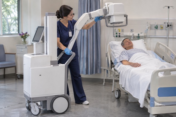
A portable X-ray system may spend much of its operating time waiting for the next examination, yet its most demanding electrical event can occur within a short exposure interval. The battery must support the intended imaging workflow without excessive voltage drop, unexpected shutdown or disruption to the generator and control electronics.
For medical equipment manufacturers, this creates two separate design questions: how much usable energy is needed between charges, and what electrical load must the battery actually deliver during an exposure?
The answers depend on the X-ray system’s power architecture. A handheld dental unit, a compact portable radiography generator and a wheeled mobile radiography system may have very different battery arrangements. Some rely on an internal rechargeable pack, while others use battery-assisted converters, intermediate energy storage or an external power supply.
A suitable portable X-ray battery pack therefore starts with the equipment’s electrical requirements and operating sequence, rather than a cell capacity selected in isolation.
Featured Snippet: How Should Medical OEMs Design a Portable X-Ray Battery Pack?
A portable X-ray battery pack should be specified using the system’s voltage range, measured energy consumption, peak battery-side load, exposure duty cycle, charging requirements and available installation space. OEMs must also identify whether intermediate energy storage supplies the exposure pulse. Cell selection, BMS protection, thermal design and safety validation should then be matched to the complete medical equipment architecture.
Table of Contents
- How Portable X-Ray Systems Use Battery Power
- Energy Capacity and Peak Power Are Different Design Requirements
- How to Estimate Battery Capacity for Portable Radiography
- Choosing Lithium Cells and Battery Pack Architecture
- BMS, Charging and Thermal Management
- Safety and Compliance Considerations for Medical OEMs
- Portable X-Ray Battery Pack Requirements for Medical OEMs
1. How Portable X-Ray Systems Use Battery Power
The term portable X-ray equipment covers several distinct product categories. Battery requirements can differ substantially between them.
Handheld radiography units integrate the X-ray source, power electronics and user controls into a compact enclosure. Weight, handling, charging access and battery retention are significant design constraints. Handheld dental X-ray units are one established example, although their intended use and radiation protection requirements must be assessed separately from general radiography equipment.
Compact portable radiography systems may use a generator that can be transported between examination locations. Depending on the design, the generator may operate from an internal battery, an external supply or a combination of power sources.
Mobile radiography systems usually have a larger equipment platform. Their electrical loads can include the generator, computing hardware, display, detector charging and, where fitted, motorized movement. A battery serving these functions may have a different discharge profile from one supplying only the imaging electronics.
FDA documentation has long distinguished battery-powered, capacitor-powered and direct-line-powered mobile radiographic systems. [1]
Where the Battery Fits in the Power Architecture
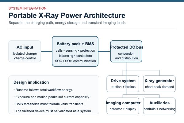
In one architecture, the battery supplies a regulated power converter that supports the X-ray generator. In another, the battery charges an intermediate energy-storage stage, which subsequently delivers a short-duration high-power pulse. Other systems may use line power for some functions while retaining a battery for mobility or backup.
The path between the battery and X-ray tube is not necessarily direct.
Research on a supercapacitor-assisted mobile X-ray system has demonstrated an architecture in which stored electrical energy supports the high instantaneous demand associated with X-ray generation. This is evidence that such designs are technically feasible, not proof that every commercial portable system uses them. [2]
For battery specification, the useful question is:
What current and voltage waveform appears at the battery terminals during the complete imaging sequence?
That waveform may include converter startup, energy-storage recharge, exposure-related transients and ordinary electronic loads. It is the battery-side requirement that must be compared with the cell and pack discharge ratings.
2. Energy Capacity and Peak Power Are Different Design Requirements
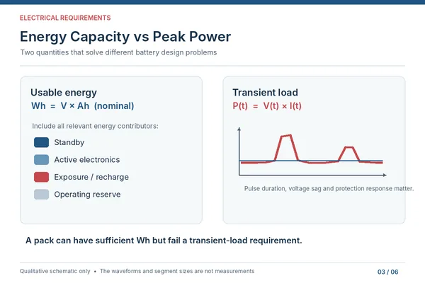
Battery capacity is often expressed in ampere-hours (Ah), while stored energy is expressed in watt-hours (Wh). Both are useful, but neither describes the complete electrical behavior of an X-ray system.
The nominal energy of a battery pack can be estimated as:
Nominal energy (Wh) = Nominal pack voltage (V) × Rated capacity (Ah)
This calculation describes nominal stored energy. The energy that the medical device can actually use will depend on voltage limits, temperature, current demand, conversion losses, cell aging and the permitted state-of-charge window.
Peak power introduces another requirement:
Battery-side electrical power (W) = Battery terminal voltage (V) × Battery current (A)
For a rapidly changing load, voltage and current must be evaluated over the relevant time interval. A single nominal-voltage calculation is insufficient to establish transient performance.
X-Ray Generator Power Is Not the Same as Battery Output Power
An X-ray generator’s rated output describes the electrical performance of the generator under specified conditions. It should not automatically be treated as the peak power demanded from the battery.
The high-voltage conversion stage has its own efficiency and operating behavior. If a suitable intermediate energy-storage stage is incorporated, energy may be accumulated before an exposure and released over a much shorter interval.
In that case, battery demand during storage recharge can differ greatly from the electrical demand at the X-ray tube during exposure.
The distinction also applies to radiographic exposure settings. Tube voltage in kVp, tube current in mA and the exposure quantity in mAs describe aspects of X-ray generation. They are not interchangeable with battery voltage, battery current or battery capacity in mAh.
A medical OEM should provide the battery supplier with measured or properly modeled battery-input load profiles. Relevant information includes:
- Continuous power during standby and active operation
- Peak input current and its duration
- Converter startup and inrush behavior
- Recharge demand following an exposure
- Minimum permissible input voltage
- Recovery time before another exposure
A pack with enough nominal Wh may still perform poorly if its internal resistance, interconnections or protection thresholds cannot accommodate the specified transient load.
Conversely, specifying an unnecessarily high battery discharge rating can increase cost, size or design complexity without improving system performance.
3. How to Estimate Battery Capacity for Portable Radiography
The starting point for battery sizing should be a representative examination workflow.
For example, a radiography system may remain powered while the operator positions the equipment, prepares the patient, reviews acquisition settings, performs an exposure and processes the resulting image. The generator is only one contributor to total energy consumption.
Displays, processors, wireless communication modules and detector interfaces may continue consuming power between exposures. Motorized movement can add another load in mobile systems.
A manufacturer-specific example illustrates why operating assumptions matter. Carestream’s published hardware guide for its DRX-Revolution Nano describes battery operation in terms of both typical exposures and continued operation of the system computer. These figures are tied to the manufacturer’s defined conditions and should not be transferred to another device. [3]

Build an Energy Budget From the Actual Workflow
A practical energy assessment should include:
Standby energy. Measure the system’s consumption while powered on but not acquiring images. Standby duration can be a substantial part of the operating cycle.
Active electronics. Include display operation, processing, detector-related loads, communications and any cooling or auxiliary functions powered by the same pack.
Exposure-related energy. Determine the energy drawn from the battery during the complete exposure and recovery sequence. Where an intermediate storage stage is present, include its recharge demand without counting the same energy twice.
Conversion losses. Account for losses in the relevant power conversion stages. Measurements taken directly at the battery terminals already include downstream consumption and conversion losses reflected at that boundary.
Usable capacity. Apply the permitted voltage and SOC limits, together with appropriate allowances for temperature and battery aging.
Operating reserve. Establish the minimum remaining energy required to finish the current procedure, protect essential equipment functions or support a controlled shutdown.
The resulting energy requirement can then be compared with the usable energy of candidate packs under specified operating conditions.
Why Exposure Count Cannot Be Calculated From Ah Alone
Two systems with similar nominal battery capacities may achieve different examination counts because their standby consumption, exposure settings, conversion efficiency and charging behavior differ.
Even within one device, the result depends on the imaging protocol and time between examinations.
A claim such as a fixed number of exposures per charge is meaningful only when accompanied by clearly defined test conditions.
For OEM development, a measured imaging workflow is more useful than an unsupported exposure-count estimate.
4. Choosing Lithium Cells and Battery Pack Architecture
Cell format, electrochemical composition and pack architecture should be considered separately.
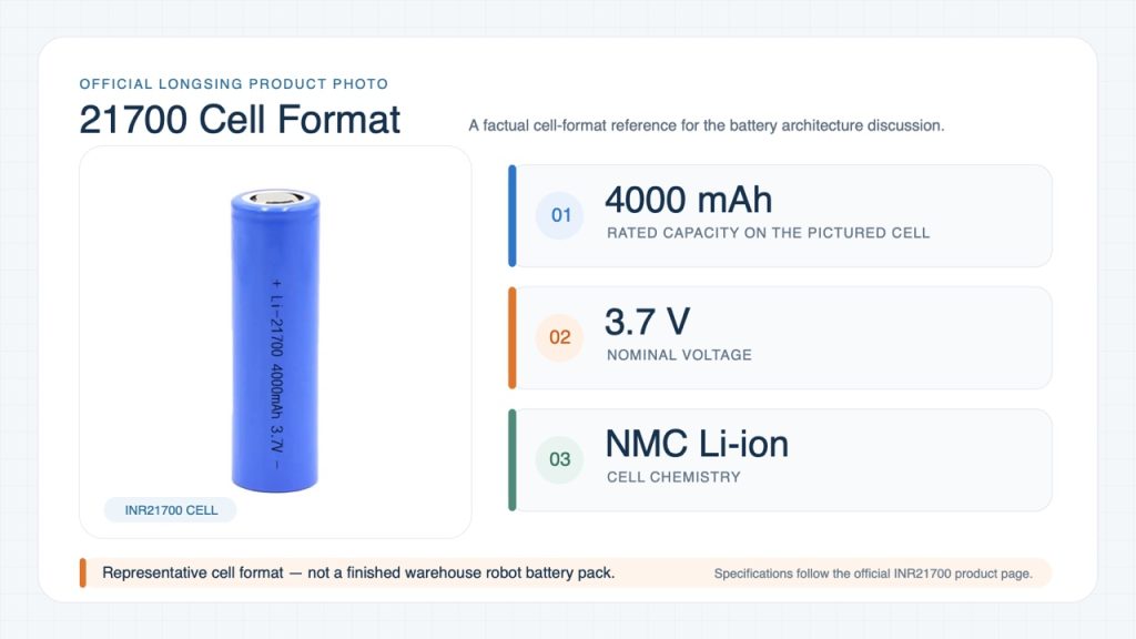
An 18650 or 21700 designation identifies a cylindrical cell size. It does not, by itself, establish the cell’s chemistry, allowable discharge current, safety qualification or suitability for medical equipment.
18650 and 21700 Lithium-Ion Cells
18650 lithium-ion cells provide a familiar cylindrical format for modular battery designs. Multiple cells can be configured in series and parallel to meet a required electrical specification, subject to the selected cells’ operating limits.
21700 cells offer a larger cylindrical format, which can be useful when a design calls for greater energy per cell or a different balance between cell count and packaging space.
However, a larger cell does not automatically provide a higher permissible discharge rate. Capacity-oriented and power-oriented cells may behave very differently under pulsed loading.
For portable X-ray equipment, the selection should account for:
- Available pack volume and mass
- Continuous and transient current requirements
- Heat generated during operation
- Voltage behavior near end of discharge
- Charging limits and expected service conditions
- Manufacturing consistency and cell traceability
LONGSING lists both 18650 lithium-ion cells and 21700 lithium-ion cells in its rechargeable battery portfolio.
These are potential starting points for OEM evaluation, not evidence that a specific cell has been qualified for an X-ray device.

Where LiFePO4 May Be Considered
Lithium iron phosphate (LiFePO4) is another rechargeable battery chemistry that can be evaluated for medical equipment.
Its electrical characteristics, voltage profile, energy density and operating requirements differ from those of common higher-voltage lithium-ion chemistries.
LiFePO4 may be worth considering when the mechanical envelope, system voltage and lifecycle targets are compatible with its characteristics. The appropriate choice still depends on the exact cell specification and complete pack design.
No lithium chemistry should be described as universally safe or suitable for every radiography application.
Series, Parallel and Mechanical Configuration
Series connections establish pack voltage, while parallel arrangements influence capacity and current-sharing capability.
Actual current handling also depends on cell impedance, conductive paths, protective devices, thermal conditions and manufacturing quality.
Cell consistency becomes particularly relevant in multi-cell packs. Capacity variation and resistance differences can affect voltage distribution, heating and usable pack performance.
For additional technical background, see LONGSING’s guide to battery cell matching.
5. BMS, Charging and Thermal Management
A battery management system should be specified against the medical device’s electrical interface and fault-response requirements.
Typical protection functions include cell overvoltage, undervoltage, overcurrent and temperature monitoring. Multi-series-cell packs may also require balancing to maintain acceptable cell-voltage distribution during use and charging.
Protection thresholds must be coordinated with the device’s normal load profile.
For instance, a short converter-startup event should not cause an unnecessary shutdown, but the protection system must still respond appropriately to a genuine fault. That distinction requires measured load data, validated thresholds and fault testing.
Battery Status and System Communication
Fuel gauging is another consideration.
A simple battery voltage reading may be an unreliable indication of remaining runtime when the load changes rapidly or the pack has aged. Systems requiring dependable charge indication may need current integration, cell modeling and calibration over the intended operating range.
Where host communication is required, the OEM should define the interface, reported parameters, fault codes and expected behavior when communication is lost.
The medical system, rather than the battery pack alone, determines what actions are appropriate after a battery warning.
Charging and Thermal Integration
Charging requirements should cover the charger type, charging temperature range, connector arrangement and whether the equipment must operate while connected to external power.
If charging and imaging can occur simultaneously, the power-path arrangement needs system-level validation. The charger, battery and generator must be coordinated so that normal operation does not exceed component ratings or compromise fault protection.
Thermal analysis should consider the cells, conductive connections, BMS power components and neighboring electronics. The resulting pack temperature depends on the installed configuration, not simply the ambient temperature or the cell datasheet.
Mechanical retention, cable routing, access for authorized servicing and the equipment’s cleaning procedures should also be addressed during integration.
6. Safety and Compliance Considerations for Medical OEMs
Medical X-ray equipment involves several layers of safety and regulatory requirements. Battery-level testing, finished-equipment evaluation, radiation protection and transport qualification have different purposes.
They should be documented separately.
IEC 60601 and Finished Medical Equipment
IEC 60601-1 addresses the basic safety and essential performance of medical electrical equipment and systems.
For radiography applications, additional standards may apply according to the equipment’s intended use. IEC 60601-2-54:2022 addresses X-ray equipment for radiography and radioscopy within its defined scope, while IEC 60601-1-3 addresses radiation protection in diagnostic X-ray equipment.
Dental systems require separate consideration. Depending on the equipment classification, standards such as IEC 60601-2-65 may be relevant instead of IEC 60601-2-54.
FDA guidance identifies applicable IEC standards for different medical X-ray equipment categories. [4]
The distinction matters because an X-ray generator, an intraoral dental device and a mobile general-radiography system do not necessarily follow the same particular-standard requirements.
EMC, Battery Safety and Risk Management
IEC 60601-1-2 covers electromagnetic disturbances affecting medical electrical equipment and emissions from such equipment. [5]
For battery integration, relevant concerns can include converter switching disturbances, communication reliability, protective-circuit behavior and the susceptibility of the battery-management interface to the surrounding electrical environment.
IEC 62133-2:2017+A1:2021 specifies safety requirements and tests for portable sealed secondary lithium cells and batteries within its scope. Its applicability must be assessed for the actual battery construction and intended application. [6]
ISO 14971:2019 provides a medical-device risk-management framework. At the battery-system interface, foreseeable hazards can include unintended power loss, overheating, incorrect battery-status reporting, charging faults and failure of protective functions. [7]
These risks should be evaluated with regard to the intended use and potential consequences for the complete medical device.
Transport Qualification Is a Separate Requirement
Lithium cells and batteries are also subject to relevant dangerous-goods transport requirements.
The United Nations Manual of Tests and Criteria, subsection 38.3, contains testing provisions for lithium cells and batteries. Transport compliance does not establish clinical suitability or finished medical-device compliance. [8]
The correct compliance plan depends on the pack configuration, target markets, applicable regulations, relevant standard editions and the division of responsibilities between suppliers and the finished-device manufacturer.
A battery cell or pack must not be presented as FDA-approved or IEC 60601-certified merely because its manufacturer supplies medical-equipment projects.
Likewise, component documentation cannot replace the required evaluation of the finished X-ray system.
7. Portable X-Ray Battery Pack Requirements for Medical OEMs
Battery development becomes more efficient when the initial specification is based on the electrical requirements of the complete imaging device.
A medical OEM does not necessarily need to finalize the cell model before contacting a battery supplier. It does need to describe the operating environment, expected loads, mechanical constraints and safety requirements clearly enough for engineering assessment.
Portable X-Ray Battery Design Parameters and Their Engineering Implications
| Design Parameter | Why It Matters | Information OEMs Should Provide | Validation Requirement |
|---|---|---|---|
| System voltage range | Determines series configuration and converter compatibility | Nominal, minimum and maximum input voltages | Voltage compatibility across operating conditions |
| Required energy | Establishes the usable energy budget | Measured workflow energy and operating reserve | Runtime under representative duty cycles |
| Average electrical load | Influences sustained discharge and temperature | Standby and active power measurements | Continuous-load and thermal testing |
| Peak electrical load | Determines transient current capability | Battery-side current waveform and event duration | Voltage sag and protection-response testing |
| Imaging duty cycle | Affects energy use and recovery demand | Exposure sequence, intervals and recharge behavior | Repeated-workflow operation |
| Mechanical envelope | Limits cell arrangement and structural design | Available dimensions, mounting and connector locations | Fit, retention and mechanical evaluation |
| Weight target | Influences cell and enclosure selection | Maximum allowable mass | Assembly mass and handling assessment |
| Charging requirements | Defines charger and power-path integration | Charge source, time target and operation-while-charging needs | Charging and combined-operation tests |
| Temperature range | Affects capacity, charging and protection | Operating, charging and storage conditions | Environmental and thermal evaluation |
| BMS communication | Determines monitoring and host integration | Required signals, interface and fault behavior | Communication and fault-injection tests |
| Service-life target | Establishes aging and replacement criteria | Cycles, calendar life and end-of-life limits | Aging and lifecycle qualification |
| Target market and compliance | Defines the regulatory evidence required | Countries, intended use and applicable requirements | Documented compliance and system verification |
From Specification to Prototype Validation
After establishing the requirements, the OEM and battery supplier can evaluate candidate cells, electrical configurations, protection circuitry, mechanical packaging and charging interfaces.
The prototype should then be tested in the actual equipment or a representative, validated system-level test arrangement.
Important conditions include low battery charge, aged-cell behavior, repeated imaging sequences, permitted temperature extremes, charging operation and defined fault scenarios.
Testing should verify both battery limits and the medical system’s response when those limits are approached.
For manufacturers considering a custom solution, LONGSING provides lithium-ion battery pack development covering configurable cell arrangements, mechanical integration and BMS-related requirements.
Medical imaging projects would require separate application-specific engineering review, component qualification and finished-device validation.
For a related discussion of general medical battery integration, see Portable Ultrasound Battery Pack Design. The X-ray application adds particular attention to exposure-related power conversion and intermediate energy storage.
Conclusion: Specify the Power Architecture Before the Battery Pack
A well-defined portable X-ray battery project begins with the power architecture and measured operating sequence.
Usable energy determines how long the equipment can support its intended workflow. Battery-side peak current, voltage stability, recharge behavior and protection coordination determine whether it can do so reliably.
These requirements must be evaluated alongside the mechanical design, charging arrangement and applicable medical-equipment safety framework.
LONGSING’s rechargeable cell and custom battery pack portfolio provides potential options for OEM development. Any proposed medical imaging application would still need technical evaluation and appropriate validation before suitability or compliance could be claimed.
Frequently Asked Questions
Click to explore more information about portable X-ray battery pack design
1. What type of battery is used in portable X-ray equipment?
Portable X-ray equipment may use rechargeable lithium-ion, LiFePO4 or other battery technologies, depending on the equipment design. Some systems also employ intermediate energy storage or external power. No single battery type applies to every portable X-ray device.
2. How do you size a portable X-ray battery pack?
Start with the system voltage range, measured battery-side energy consumption, intended imaging workflow and required operating reserve. Then verify transient current capability, temperature performance, usable capacity and charging constraints.
3. Why is peak power important for medical imaging equipment?
Exposure-related power conversion and other transient events may create electrical loads substantially different from the average operating load. The pack must maintain acceptable voltage and protection behavior during the specified battery-side current waveform.
4. Do all portable X-ray systems draw exposure power directly from the battery?
No. Some architectures employ an intermediate energy-storage stage, while others use different converter or external-power arrangements. The battery’s actual exposure-related load must be determined from the specific system design.
5. Are 18650 or 21700 cells suitable for medical imaging devices?
They can be considered as candidate cell formats, but suitability depends on the selected cell’s electrical ratings, mechanical integration, battery protection and project-specific qualification. Cell size alone does not establish medical suitability.
6. What BMS functions are important for portable X-ray systems?
Relevant functions can include voltage, current and temperature protection, cell balancing, fuel gauging, fault reporting and charger coordination. The required functions depend on the pack configuration and the medical device’s safety architecture.
7. Which safety standards should medical battery OEMs consider?
Depending on the project, IEC 62133-2 may be relevant for portable lithium battery safety, while IEC 60601 standards and ISO 14971 relate to medical-equipment evaluation and risk management. UN 38.3 addresses lithium battery transport testing. Applicability must be confirmed for the intended device and market.
8. What specifications are needed for a custom medical battery pack?
OEMs should provide voltage limits, energy requirements, continuous and peak battery loads, imaging duty cycle, dimensions, mass target, temperature range, charging requirements, BMS interfaces, service-life targets, target markets and applicable compliance requirements.
References
[1] U.S. FDA — Routine Compliance Testing Procedures for Diagnostic X-Ray Systems, Part IV: Mobile Radiographic Systems. ↵
Supports the distinction between battery-powered, capacitor-powered and direct-line-powered mobile radiography systems.
[2] Safety Evaluation of Mobile X-Ray Equipment Using Super-Capacitor (PMID: 30412517). ↵
Supports the discussion of intermediate energy storage and why exposure-related peak power is not necessarily supplied directly by the battery.
[3] Carestream Health — DRX-Revolution Nano Mobile X-ray System Hardware Guide (2018). ↵
Supports the explanation that battery runtime and exposure-count estimates depend on specific equipment designs and operating conditions.
[4] U.S. FDA — Medical X-Ray Imaging Devices: Conformance with IEC Standards (2023). ↵
Supports the distinction between applicable safety standards for different categories of medical X-ray equipment.
[5] IEC 60601-1-2:2014+A1:2020 — Electromagnetic Disturbances: Requirements and Tests. ↵
Supports the discussion of electromagnetic compatibility requirements for medical electrical equipment and systems.
[6] IEC 62133-2:2017+A1:2021 — Safety Requirements for Portable Secondary Lithium Cells and Batteries. ↵
Supports the discussion of lithium battery safety requirements and their applicability to qualifying portable battery designs.
[7] ISO 14971:2019 — Medical Devices: Application of Risk Management to Medical Devices. ↵
Supports the evaluation of battery-related hazards, including unexpected power loss, thermal faults and charging failures.
[8] UN Manual of Tests and Criteria, Subsection 38.3 — Lithium Battery Transport Testing. ↵
Supports the distinction between lithium battery transport testing and medical equipment safety compliance.