
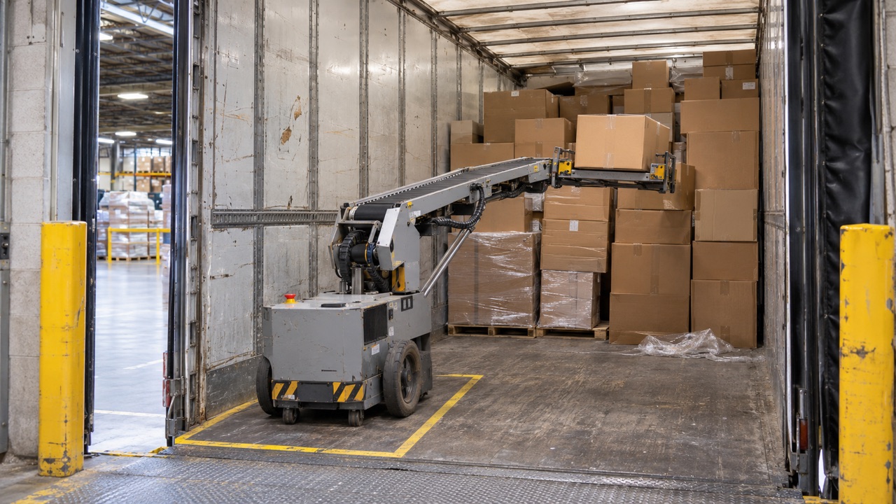
A truck trailer may contain hundreds of cartons, but unloading them rarely involves hundreds of identical movements. Box weights vary, stacks shift during transport, and the robot may need to change its reach or gripping position several times within a single unloading cycle.
For a battery-powered unloading robot, those movements create an uneven electrical load. The robotic arm, mobile base, gripper and onboard computers may draw power at the same time, followed by periods of much lower consumption.
This makes warehouse unloading robot battery selection a matter of matching the pack to the actual work cycle, rather than choosing capacity from the number of hours printed on a specification sheet.
Recent developments in warehouse robotics bring this into focus. On November 3, 2026, Boston Dynamics introduced Stretch Gen 2, reporting unloading speeds of up to 1,000 cases per hour under suitable conditions, battery operation across two shifts, and charging to 90% in approximately 75 minutes. These are manufacturer-reported figures for Stretch Gen 2, not general specifications for unloading robots. 【1】
The practical challenge for an OEM is to define a battery system that can sustain the required unloading rate, handle repeated motor-current peaks and recover enough energy during the warehouse’s available charging windows.
Featured Snippet: How Should an OEM Select a Warehouse Unloading Robot Battery?
A warehouse unloading robot battery should be sized using the robot’s measured operating cycle, required usable energy, continuous and peak current, acceptable voltage range and charging schedule. Cell chemistry, BMS communication, thermal performance and mechanical integration also need to be verified. The final pack should be tested under representative unloading conditions, including repeated arm movements and simultaneous electrical loads.
Table of Contents
- How Warehouse Unloading Robots Use Battery Power
- Sizing Battery Runtime and Peak Power
- Fast Charging and Warehouse Fleet Uptime
- Cell Selection, BMS and Pack Integration
- What OEMs Should Specify for a Custom Battery Pack
1. How Warehouse Unloading Robots Use Battery Power
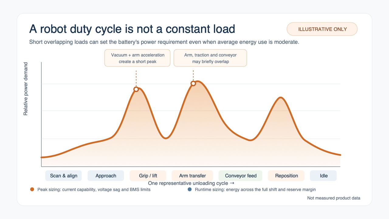
An unloading robot does not operate at a steady load throughout its shift. Its electrical demand changes with carton weight, robot movement, gripping method and the time spent between picks.
The operating cycle is a useful starting point for understanding where the battery’s energy goes.
Robotic Arm and Gripper Loads
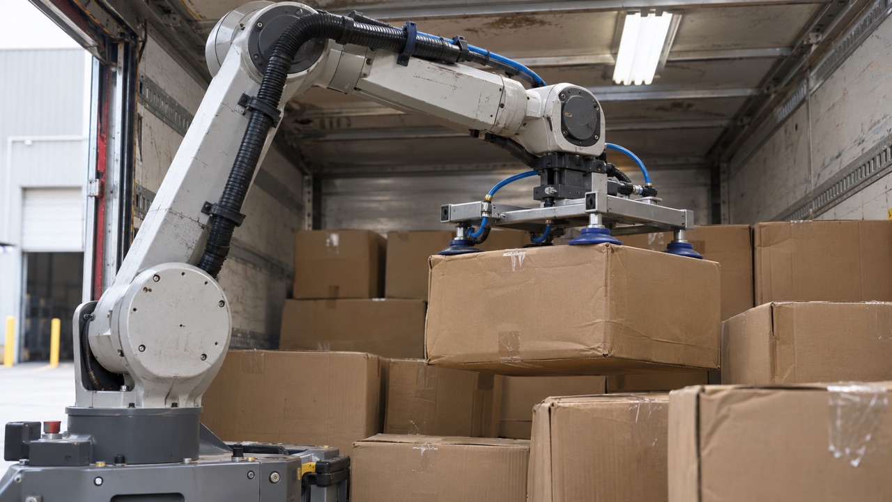
During unloading, the arm repeatedly extends, lifts, rotates and retracts. Each movement places different demands on its joint motors.
Reaching a carton near the trailer roof, for example, may require a different combination of joint torques from collecting one at floor level. The motor current also changes as the arm accelerates, carries the carton and decelerates before release.
The gripping system adds another load.
A robot equipped with a vacuum gripper may use pumps, valves and related controls to hold and release cartons. Mechanical grippers and other end effectors have different consumption patterns. Their contribution must be measured for the specific machine.
On a fast unloading cycle, several of these loads can overlap.
Research into collaborative robotic systems has shown that movement speed and acceleration affect both energy consumption and peak power. Faster movement may shorten task duration while increasing instantaneous electrical demand. The outcome varies with the machine and motion profile. 【2】
This distinction matters when a robot is expected to maintain a high case-handling rate for hours rather than complete a few isolated picks.
Mobile Base and Auxiliary Equipment
The mobile base consumes power when the robot moves between unloading positions, accelerates or corrects its alignment.
Traction demand may also change with floor conditions, robot mass and the movement profile.
Meanwhile, cameras, onboard computing, communications, controllers and safety-related electronics can remain active while the arm is waiting for its next task.
These auxiliary loads are easy to overlook when battery sizing is based mainly on motor ratings.
For a robot that regularly encounters pauses between groups of cartons, standby energy can represent a measurable part of the shift’s total consumption.
Operating Modes and Battery Design Implications
| Operating Mode | Typical Load Behaviour | Battery Design Concern |
|---|---|---|
| Standby and sensing | Continuous electronic loads | Background energy consumption |
| Robot repositioning | Variable traction current | Voltage stability and current demand |
| Arm lifting and acceleration | Short motor-current peaks | Pulse discharge capability |
| Gripping and releasing | Repeated end-effector loads | Load repetition and thermal effects |
| Continuous unloading | Overlapping motor and auxiliary loads | Sustained energy demand and heating |
| Charging between shifts | Controlled charging current | Charge acceptance and charger integration |
The table describes typical engineering considerations, not a fixed load profile for every unloading robot.
A mobile robot with an integrated conveyor, for instance, may have different electrical requirements from a machine that transfers cartons to a separately powered conveyor.
Before selecting the pack, the OEM needs to establish exactly which components draw power from the onboard battery.
2. Sizing Battery Runtime and Peak Power
Battery capacity is often the first parameter discussed during an OEM project. For unloading robots, it is more useful to begin with a recorded operating cycle.
Motor ratings can identify potential high-power loads, but they do not show how long each load operates or how much energy the robot consumes during a normal unloading sequence.
Calculate Runtime from a Representative Duty Cycle
A useful test should include different carton weights, arm positions, robot movements and waiting periods.
Where possible, energy should be measured directly at the battery terminals.
The basic relationship is:
Required usable energy (Wh) = Average battery-terminal power (W) × Required operating time (h)
The calculation gives the energy the robot must be able to draw during the specified period.
Nominal battery capacity will usually need to be higher because the complete rated energy is not necessarily available within the permitted operating window.
Battery aging, low-temperature performance, workload variation and the minimum required end-of-shift reserve also need consideration.
Example: Estimating Battery Energy for an Unloading Shift
The following is a hypothetical calculation for illustrating the method. It is not a LONGSING product specification or a reported customer test.
Assume a prototype unloading robot is tested through a representative 90-minute cycle that includes active box handling, repositioning and short waiting periods.
The battery-terminal energy log records:
- Energy consumed during the test: 2.25 kWh
- Test duration: 1.5 hours
- Required operating period: 4 hours
- Planned usable SOC fraction: 80%
- Assumed end-of-life capacity retention: 85%
Average battery power is:
2.25 kWh ÷ 1.5 h = 1.5 kW
For four hours of equivalent operation:
1.5 kW × 4 h = 6.0 kWh
Applying the assumed usable SOC window and end-of-life capacity factor:
6.0 kWh ÷ (0.80 × 0.85) ≈ 8.82 kWh
The preliminary nominal energy estimate is approximately 8.8 kWh, before any additional project-specific reserve.
Because the original measurement was taken at the battery terminals, it already reflects the electrical losses present during that test. Applying another generic conversion-efficiency factor to the same energy measurement would risk double-counting those losses.
The calculation is only an initial sizing estimate. It does not establish the required voltage, allowable current, cell configuration or pack dimensions.
Those requirements must be evaluated separately.
Why Peak Current Can Limit Robot Performance
A robot may have enough usable energy remaining to complete its shift but still encounter problems during a demanding pick.
Consider an unloading sequence in which the robot base moves while the arm accelerates with a heavy carton and the gripping system remains active.
The combined demand can briefly push battery current well above the average load.
Current flowing through the cells and pack connections produces a voltage drop. In a simplified resistance model:
Voltage drop ≈ Current × Effective resistance
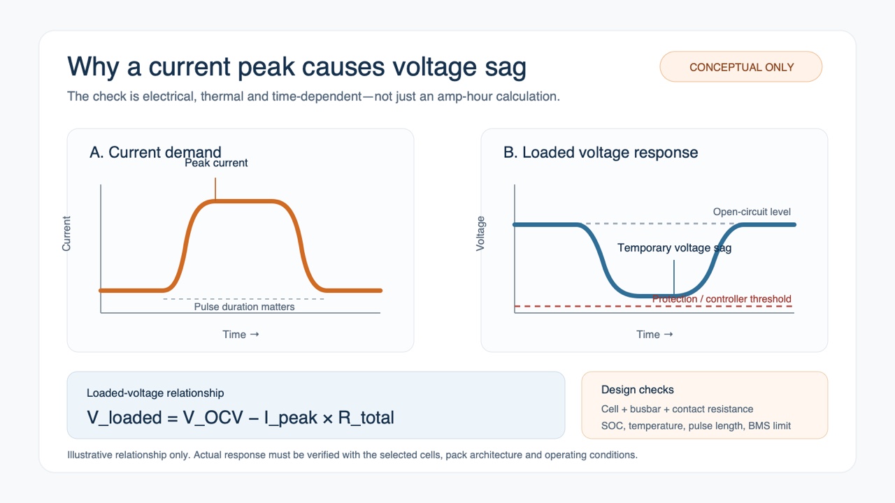
The actual voltage response is influenced by cell chemistry, state of charge, temperature, pulse duration and battery condition.
If the loaded voltage falls below the operating limit of the motor controller, or the BMS reaches a configured protection threshold, the robot may slow down or stop even though the pack still contains stored energy.
A battery specification therefore needs more than an Ah or Wh rating.
The OEM should define continuous current, peak-current magnitude, pulse duration, repetition frequency and minimum acceptable loaded voltage.
Repeated pulses also deserve attention. A pack that handles one short lifting event at room temperature may behave differently after sustained operation inside a warm enclosure.
Cell selection and interconnection design must reflect those conditions.
For multi-cell packs, consistent cell characteristics help prevent an individual cell group from limiting usable performance. LONGSING’s guide to battery cell matching discusses the relevance of capacity, open-circuit voltage and internal resistance during pack assembly.
The finished battery still needs load testing with its actual BMS, connections and enclosure.
3. Fast Charging and Warehouse Fleet Uptime
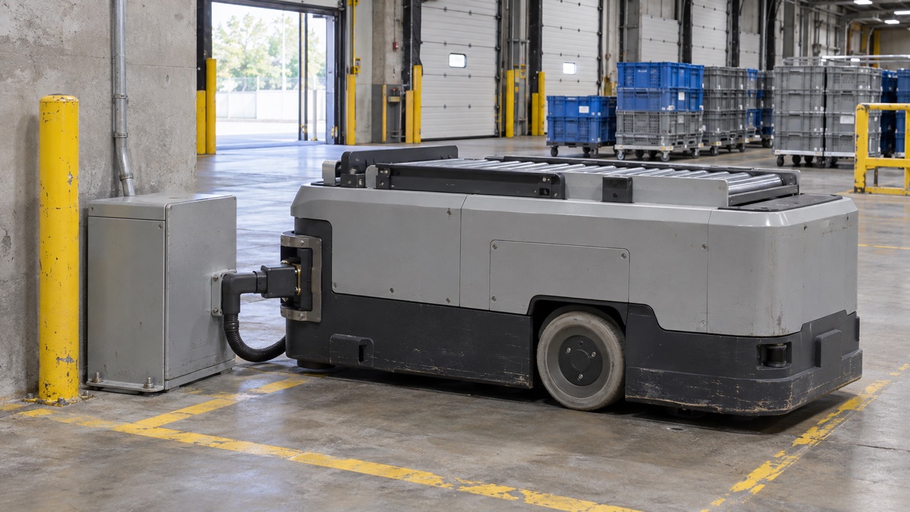
An unloading robot may be technically capable of working for several hours yet remain underutilized if its battery cannot recover enough energy before the next assigned trailer.
Charging strategy is therefore closely tied to warehouse scheduling.
A facility operating one shift has different requirements from a distribution centre where robots move between incoming trailers throughout the day.
Match Charging to the Available Downtime
There are three common approaches worth considering.
Scheduled charging uses a longer planned break, such as an overnight period. It can be practical when the battery has enough time to recover before the next operating shift.
Opportunity charging adds energy during shorter periods when the robot is not unloading. The battery may receive several partial charges rather than one complete charging session.
Battery replacement allows a discharged pack to be exchanged for a charged one, but only when the mechanical and electrical system has been designed for safe replacement. It also requires spare batteries, service access and suitable operating procedures.
The appropriate choice depends on workload and fleet organisation.
For some facilities, a larger battery with overnight charging may be sufficient. Others may benefit from shorter scheduled charging periods or a replaceable-pack architecture.
Neither higher capacity nor faster charging automatically produces better fleet utilisation.
Fast Charging Has Electrical and Thermal Limits
Charging time depends on the selected cells, charger output, initial SOC, target SOC and temperature.
A high-power charger cannot force a battery to accept more current than its approved charging profile permits.
During charging, the BMS must monitor relevant cell and pack conditions, while the charger follows the validated voltage and current limits.
The charging profile may also reduce current as the battery approaches its upper voltage or SOC limits.
Research on fast charging and lithium plating shows that charging rate, temperature and SOC can affect plating behavior in lithium-ion cells using graphite-based negative electrodes. 【3】
Charging performance should therefore be evaluated across the intended operating temperature range and battery life, rather than measured only with a new pack under favourable laboratory conditions.
For fleet planning, the relevant question is often how much usable energy can be recovered during a 30-minute or 60-minute charging window, rather than how quickly the battery reaches 100%.
Those time windows are examples of possible warehouse scheduling constraints, not charging claims for a LONGSING product.
Planning Battery Capacity Around Shifts
A warehouse operator can use unloading records to determine whether a robot needs to complete an entire shift without charging or can reliably recharge between assignments.
The charging plan should account for queueing at charging stations, simultaneous charger demand and the amount of energy required for the next job.
Battery aging is another practical consideration. A charging schedule that works with a new battery may not provide the same usable operating time near the end of its planned service life.
For an OEM, these operating assumptions belong in the battery specification before the first prototype is built.
4. Cell Selection, BMS and Pack Integration
After the electrical load and charging plan are defined, the next decision is how to build the battery pack.
Cell chemistry, physical format and series/parallel configuration all affect the result, but they describe different aspects of the design.
Choosing Between 18650, 21700 and LiFePO4 Options
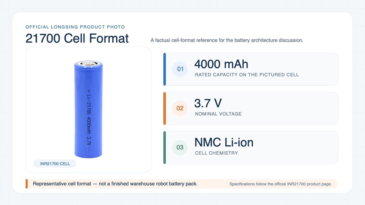
18650 and 21700 are cylindrical cell formats. LiFePO4 is a lithium-ion chemistry that may be available in different physical cell formats.
An OEM should first consider the required voltage, energy, power, service life and charging characteristics.
The physical cell format can then be evaluated against enclosure geometry, cell count, thermal management and assembly requirements.
18650 cells can provide layout flexibility where battery space is restricted or irregular.
21700 cells may reduce the number of individual cells needed to achieve a particular energy target, depending on the cell models being compared.
LONGSING offers 21700 lithium-ion battery cells for consideration in custom rechargeable pack designs.
LiFePO4 is another option where its operating characteristics suit the project, although pack weight, volume, voltage and charging performance still need evaluation.
No cell format or chemistry can be identified as the best choice for every unloading robot without the complete load and installation specification.
For additional discussion of physical cell architecture, see LONGSING’s comparison of 18650, 21700 and prismatic cells.
BMS Communication with the Robot Controller
A warehouse unloading robot normally requires battery protection and usable information about battery operating conditions.
Depending on the design, BMS functions may include:
- Cell voltage, pack current and temperature monitoring
- Overcharge, overdischarge and overcurrent protection
- Cell balancing
- State of charge (SOC) estimation
- State of health (SOH) information
- Fault reporting and charging control
Battery health monitoring and fault diagnosis are established subjects in lithium-ion battery prognostics and health management research. 【4】
For an unloading robot fleet, reported SOC and battery faults can help the controller or fleet-management system make decisions about task assignment and charging.
However, the required data must be defined in the system design.
A BMS using CAN or RS485 is not automatically compatible with an existing robot controller merely because both devices have the same physical interface.
Communication messages, data definitions, update intervals and fault responses need to be agreed between the battery supplier and robot manufacturer.
LONGSING’s article on CAN vs RS485 BMS communication explains these differences for industrial battery integration.
Mechanical Installation and Thermal Behaviour
An unloading robot battery may experience repeated acceleration, vibration and changes in mechanical loading as the machine moves around a trailer or loading dock.
The enclosure, mounting points, connectors and wiring need to withstand the intended operating environment.
The pack should also provide a suitable thermal path for heat generated during repeated high-current operation and charging.
A layout that fits within the available compartment is not automatically thermally suitable.
Particular attention may be needed around densely packed cells, busbars, BMS components and cable connections.
Battery mass and placement can also affect the robot’s stability and available space for other equipment.
These issues are best resolved while the mechanical and electrical designs are still being developed, rather than after the enclosure dimensions have been fixed.
LONGSING Custom Lithium Battery Pack Development
For robot manufacturers developing a new power system, LONGSING’s custom lithium-ion battery pack solutions provide a starting point for discussing rechargeable cell selection, series/parallel configuration, BMS integration and mechanical requirements.
The final design would need to be evaluated against the robot’s measured current profile, available installation space, charging method and target operating conditions.
This approach is particularly relevant where a standard battery pack does not match the robot’s electrical and mechanical requirements.
5. What OEMs Should Specify for a Custom Warehouse Robot Battery Pack
A request for a high-capacity lithium battery is not enough to begin a reliable unloading robot pack design.
The battery supplier needs to understand how the machine works, what electrical limits it must respect and how it will be charged.
Warehouse Robot Battery Specification Checklist
| Parameter | Information to Provide | Why It Matters |
|---|---|---|
| System voltage | Nominal and full operating-voltage range | Controller compatibility |
| Energy and runtime | Measured Wh, target operating hours and reserve | Pack capacity sizing |
| Continuous current | Sustained load requirements | Cell and thermal selection |
| Peak current | Maximum current, duration and frequency | Pulse capability and voltage sag |
| Unloading duty cycle | Carton handling rate, load variation and standby time | Representative energy demand |
| Battery dimensions | Available length, width, height and weight limit | Cell layout and enclosure |
| Charging strategy | Available charging window and charger specifications | Cell and charging-system selection |
| Communication | CAN, RS485 or another interface with protocol details | BMS and controller integration |
| Environment | Temperature, vibration, shock, dust and moisture exposure | Mechanical and thermal design |
| Service life | Operating schedule and expected charging frequency | Cell and aging evaluation |
| Compliance | Destination markets and applicable requirements | Validation and certification planning |
Actual current logs, mechanical drawings and information about the robot’s charging architecture are especially valuable during the initial evaluation.
If electrical measurements are not yet available, motor specifications and a representative unloading sequence can help define a test plan.
Safety and Transport Requirements
Safety and compliance requirements must be determined for the finished battery system and its target market.
IEC 62619:2022 specifies safety requirements for secondary lithium cells and batteries used in industrial applications, including certain motive applications. Its applicability to a particular unloading robot must be assessed against the complete equipment design. 【5】
Transported lithium cells and batteries are also subject to relevant transport provisions. The UN Manual of Tests and Criteria, Revision 8, together with Amendment 1, includes requirements related to lithium batteries in subsection 38.3. 【6】
Transport testing is not a substitute for the safety evaluation of the complete robot.
A custom pack’s final compliance position depends on its construction, verified test results, intended application and destination market.
Preparing an OEM Battery Enquiry
Before contacting a battery manufacturer, the OEM should ideally have:
- The robot’s voltage and current requirements
- A representative unloading duty cycle
- Target runtime and charging schedule
- Battery compartment dimensions
- BMS and communication requirements
- Environmental and compliance expectations
- Expected sample and production requirements
These details allow the project to move from a general capacity enquiry to an engineering discussion about feasible cell and pack configurations.
6. Conclusion
Battery sizing for warehouse unloading robots starts with the cartons being handled and the way the robot moves them.
The electrical load changes as the arm accelerates, the base repositions and the gripping system operates. Average energy consumption determines the initial runtime requirement, while repeated current peaks and voltage limits influence cell and pack selection.
The charging schedule is equally important when robots are expected to work across multiple warehouse shifts.
For a new OEM project, measured unloading-cycle data, battery-compartment drawings and charger specifications provide a useful foundation for discussing a custom pack with LONGSING.
A battery designed around those inputs is easier to evaluate and validate than one selected from nominal capacity alone.
Frequently Asked Questions About Warehouse Unloading Robot Batteries
Click to explore more information about warehouse unloading robot battery design.
Q: What type of battery is suitable for a warehouse unloading robot?
A: A rechargeable lithium-ion battery system can be suitable for mobile unloading robots. The specific chemistry, cell format and pack design depend on the voltage, energy, current, installation space and charging requirements of the machine.
Q: How much battery capacity does an unloading robot need?
A: There is no universal capacity requirement. Engineers should use measured energy consumption from a representative unloading cycle, calculate the usable energy needed for the operating period, and account for battery aging and operating reserves.
Q: Why do unloading robots require high peak-current capability?
A: Robotic-arm acceleration, lifting, mobile-base movement and gripper operation can create overlapping electrical loads. The battery must support these current peaks without excessive voltage drop, overheating or unwanted BMS shutdown.
Q: Does faster box handling reduce battery runtime?
A: It can affect runtime, but the result is not determined by speed alone. Faster movements may increase peak power while reducing task duration. Total energy consumption depends on the movement trajectory, carton loads, idle time and other electrical systems.
Q: Can an unloading robot battery support fast charging?
A: Yes, if the selected cells, charger, BMS and thermal design support the intended charging profile. Permitted charging current can vary with temperature and SOC, so charging performance needs validation under the expected operating conditions.
Q: Are 21700 cells better than 18650 cells for unloading robots?
A: Neither format is universally better. 21700 cells may help reduce cell count in some designs, while 18650 cells can offer layout flexibility. The choice should be made using the selected cells’ actual electrical characteristics and the completed pack requirements.
Q: What BMS functions are important for warehouse robots?
A: The BMS should provide the protection and monitoring required by the battery design. Depending on the system, SOC, SOH, temperature, charging status and fault information may also be communicated to the robot controller or fleet-management system.
Q: What information should an OEM provide for a custom robot battery?
A: Provide the operating-voltage range, measured load profile, continuous and peak current, runtime, charging schedule, battery-space drawing, temperature and vibration requirements, BMS interface and target market. These inputs support an initial engineering feasibility assessment.
References
[1] Boston Dynamics Stretch Gen 2 manufacturer announcement. ↵
Supports the manufacturer-reported unloading rate, two-shift battery operation and 90% charging time stated above.
[2] Collaborative-robot energy consumption and motion-profile research. ↵
Supports the discussion of how robot speed and acceleration affect energy consumption and peak power.
[3] Lithium-ion fast-charging and lithium-plating research. ↵
Supports the explanation of how charging rate, temperature and SOC can influence lithium plating.
[4] Lithium-ion battery prognostics and health-management review. ↵
Supports the discussion of battery health monitoring, fault diagnosis and BMS data.
[5] IEC 62619:2022 industrial lithium-battery safety reference. ↵
Supports the industrial lithium-battery safety requirements discussed above.
[6] UN Manual of Tests and Criteria, subsection 38.3 reference. ↵
Supports the lithium-battery transport-testing discussion under UN 38.3.