
An overnight security patrol rarely follows a perfectly repeatable power profile. A robot might complete several scheduled rounds without interruption, then receive an alarm just as it is preparing to return to its charging station. Its remaining battery energy must cover the additional movement, active surveillance and the journey back to the dock.
That operating pattern makes security robot battery selection more complicated than matching a capacity rating to an expected patrol duration.
A security robot battery must support traction, cameras, navigation and computing equipment, often with several loads running simultaneously. For robots designed to charge autonomously, the battery also needs to work with a docking system that can establish a reliable electrical connection and manage charging without routine operator intervention.
Recent developments show why these requirements deserve attention. On November 10, 2026, Amazon announced Ring Rover Cam, a ground-based security robot intended for commercial premises. Its published functions include scheduled patrols, automatic investigation of alerts and video recording during movement. [1]
These capabilities illustrate the changing operating demands of mobile security equipment. Ring has not publicly established the Rover’s battery chemistry, capacity or detailed charging architecture, so those specifications should not be assumed.
For equipment manufacturers, the more useful question is how to size and integrate a rechargeable battery around the robot’s actual patrol schedule, incident-response requirements and charging arrangement.
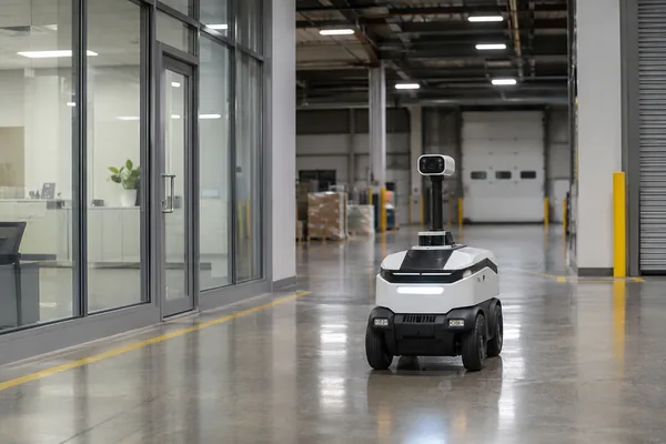
1. How Security Patrol Robots Use Battery Power
A mobile security robot draws power from more than its drive motors. Depending on the configuration, cameras, navigation sensors, wireless communication equipment and onboard processors may remain active for much of a patrol.
The motor load changes with movement. Starting from a stop, turning in a confined space or crossing a ramp can briefly increase current demand. Camera and computing loads behave differently. They may remain relatively steady while the robot moves, stops to observe an area or waits for the next scheduled route.
Consider a patrol robot monitoring a warehouse after closing. It might travel between loading bays, stop at an entrance for a camera scan and then remain stationary while transmitting video. During that stationary period, motor power may fall substantially, but surveillance electronics can continue consuming energy.
This is one reason a traction-only power estimate can be misleading when sizing a security robot battery.
Surveillance power does not disappear when the robot stops
Some security platforms maintain motion detection, network connectivity or other monitoring functions while docked. Whether those functions draw energy from the battery, an external supply or a combination of the two depends on the electrical architecture.
Ring’s Rover Cam, for example, is designed to detect person motion while docked. [1] Knightscope also describes its K5 security robot as remaining operational while charging. [2]
These are manufacturer-specific capabilities rather than features that should be assumed for every security robot. During battery sizing, engineers need to establish which systems remain powered in each state and where that power comes from.
It is also worth measuring the auxiliary load separately from the drive system. On a robot that spends considerable time stationary, the accumulated energy used by cameras, communication and computing hardware may represent a meaningful share of the mission budget.
2. Estimating Security Robot Battery Runtime from Real Operating Conditions
Battery capacity is commonly stated in ampere-hours, but ampere-hours alone do not tell an OEM how long a robot will operate. The more useful starting point is energy, expressed in watt-hours.
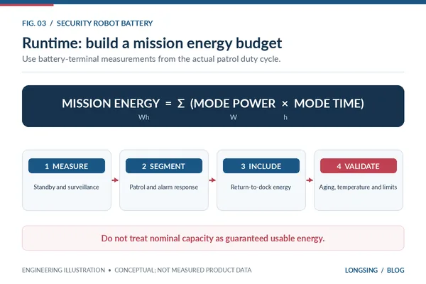
This provides a nominal energy figure, not a guarantee of the energy available under every operating condition. For a reasonably steady electrical load, a first-pass estimate is:
The difficulty in predicting security robot battery runtime lies in determining usable energy and average system power accurately. A security patrol rarely maintains a constant load. The robot accelerates, stops, turns, processes video and communicates with its monitoring system. An alarm may extend the route or activate additional equipment. Temperature and battery aging can also reduce the energy available for a mission.
Calculate energy by operating mode
A more practical approach is to divide the mission into operating periods and estimate the energy required in each one.
This method allows engineers to account for scheduled patrols, stationary surveillance, incident response and the return journey separately. The power values should come from measurements of the complete robot wherever possible. Motor specifications and processor datasheets can help with preliminary estimates, but they do not fully capture system-level losses or the interaction between loads.
The security robot battery needs to cover routine consumption while retaining enough energy for a safe return.
How much energy should be reserved for returning to the dock?
A fixed SOC threshold can be convenient for early control development, but a universal reserve percentage is difficult to justify. A robot operating near its charging station has different return-energy requirements from one working at the far end of a large facility. Temporary obstacles, route changes or a navigation retry can extend the return journey.
Battery condition matters as well. Near the end of its intended service life, a pack may provide less usable energy than it did when new. At low temperature, available power and energy may also be reduced, depending on the selected cells.
The return threshold should therefore be validated against the longest credible return route and the operating conditions specified for the robot. For applications that prioritize immediate incident response, the OEM must also decide whether a new alarm can interrupt a planned return to the dock. That decision belongs to the robot’s mission controller, supported by reliable battery information.
3. Standby, Scheduled Patrols and Alarm Response
A security robot’s daily power requirement depends heavily on how it is deployed. A robot assigned to hourly patrols may spend much of its time waiting between routes. Another platform may move more frequently, maintain continuous video recording or respond to alarms from connected security equipment.
These differences can affect both the required security robot battery capacity and the charging schedule.
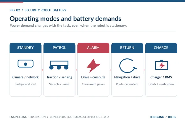
Security Robot Operating Modes and Battery Design Implications
| Operating Mode | Typical Electrical Loads | Load Characteristics | Battery Design Considerations |
|---|---|---|---|
| Standby / Monitoring | Network interface, cameras and monitoring electronics where enabled | Low or intermittent load over extended periods | Standby consumption and available operating energy |
| Scheduled Patrol | Drive motors, navigation, cameras and processors | Base load with acceleration and turning peaks | Usable energy, continuous current and voltage stability |
| Alarm Response | Traction, video processing, communication and optional lighting or siren | Potentially simultaneous loads and short current peaks | Peak discharge capability and incident-response reserve |
| Return to Dock | Drive system, localization and obstacle detection | Route-dependent energy requirement | Return-energy threshold and low-SOC behavior |
| Charging | Charger, BMS and any systems powered during docking | Controlled charging, potentially with auxiliary loads | Charging limits, connection verification and fault handling |
The table provides a starting framework. The duty cycle used for security robot battery design should reflect the intended security workflow rather than a generic robot operating profile.
Alarm response can change the load suddenly
Suppose a robot is completing its last patrol before charging. A door sensor then triggers an investigation request. Depending on the system, the robot may need to accelerate, navigate to another part of the building, operate its surveillance equipment and maintain a communication link with the monitoring platform.
The relevant battery requirement is the combined load during that response, particularly when the battery is already at a relatively low SOC. Short current peaks can produce voltage sag. If the pack, interconnections or protection settings are not suited to the load, the robot may experience a voltage-related fault even though its remaining energy appears sufficient.
Testing should therefore include representative high-load events near the minimum permitted operating SOC, rather than relying exclusively on tests with a fully charged battery.
LONGSING’s inspection robot battery guide discusses related traction and sensor-load considerations. Security patrol applications add the need to coordinate those loads with scheduled coverage and unpredictable alarms.
Charging time affects patrol availability
When a robot covers a property through repeated patrols, the charging interval becomes part of the operating schedule. Knightscope’s published information on the K5 provides one commercial example of a robot that returns to its charging station and resumes patrol after recharging. [2]
That operating model cannot be transferred directly to every robot. Charging time depends on battery capacity, the selected cells, the permitted charging current, temperature and charger capability. For a new OEM design, the practical measure is whether the robot can recover enough usable energy between scheduled missions.
4. Security Robot Battery Charging and Auto-Docking Reliability
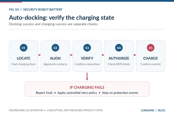
Autonomous charging removes the need for an operator to plug in the robot after every patrol. It also creates an additional integration problem: the robot must locate the charging station, make the electrical connection and confirm that charging has actually started.
A successful navigation command does not necessarily mean the battery is charging. The Nav2 docking framework makes this distinction explicit. Its charging-dock interface provides separate checks for docking contact and charging status. [3]
This separation is useful when designing a robot that may operate through the night without direct supervision.
Getting the robot into position
In a contact-based charging arrangement, the robot approaches a docking station and aligns its charging contacts with the mating interface. Localization accuracy is important, but the mechanical design is equally relevant. Repeated contact, small alignment errors, wear and contamination can affect electrical connection quality.
An adequate mechanical connection must also maintain acceptable contact resistance under the intended charging current. If resistance rises because the contacts are worn, dirty or poorly aligned, voltage drop and localized heating can become concerns.
The charger and robot controller should have a means of detecting unsuccessful connection attempts. Depending on the design, this may involve contact sensors, voltage feedback, current measurement or a combination of signals.
Confirming the charging state
After physical docking, the electrical system must determine whether charging can proceed. The sequence may involve checking battery voltage, temperature, charger readiness and any required charging permissions. In systems that support communication between the charger and BMS, the permitted current and voltage limits may also be exchanged.
A robot should not report successful charging simply because it has reached the correct docking position. It needs suitable confirmation from the electrical system. This matters during unattended operation: a robot that remains parked at the charging station without receiving charge may be unavailable when its next patrol is scheduled.
Interrupted charging and recovery
Charging failures should be treated according to their cause. If contact was not established, the robot may be able to reposition and retry. If charging stopped because of a battery temperature limit or protection event, repeatedly attempting to restart it may be inappropriate.
A communication fault requires another response, especially where battery and charger controllers depend on exchanged status information. The OEM should define how many docking retries are permitted, how a failure is reported and when the robot must stop attempting to charge.
A related question is what happens when an alarm arrives while the robot is charging. The control system needs to determine whether the robot has sufficient energy to leave the station, whether charging can be safely interrupted and how the mission will affect the next scheduled patrol. These requirements should be established before the security robot battery and charging hardware are finalized.
5. Selecting Cells and Pack Architecture for a Security Robot Battery
Once the operating profile is understood, cell selection for the security robot battery becomes more straightforward. For a security robot, the main constraints are usually available battery space, required energy, discharge current, charging frequency, operating temperature and expected service life.
The first choice concerns chemistry. The next concerns the physical cell format and pack construction.
Lithium-ion or LiFePO4?
Lithium-ion cells based on higher-energy cathode chemistries may suit a robot with tight weight or volume limits. LiFePO₄ is another option where its electrical characteristics, cycling performance and thermal behavior suit the application. Its lower nominal cell voltage and generally lower energy density need to be considered at pack level.
Neither chemistry guarantees a particular runtime or charging speed. Engineers should compare the actual cell specifications against the expected load profile, rather than selecting a chemistry based only on general claims about energy density or cycle life.
Cylindrical and prismatic cell formats
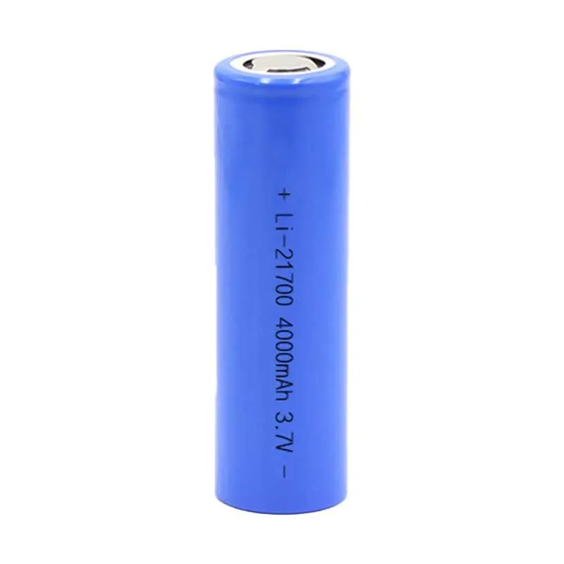
18650 and 21700 refer to cylindrical cell sizes. They are not separate battery chemistries. An 18650-based arrangement may provide flexibility where the battery compartment is narrow or irregular. The larger 21700 format can be useful when the required energy and available space make it possible to use fewer cells.
Prismatic cells offer different packaging possibilities, particularly where a rectangular battery compartment can accommodate them. The finished pack also needs mechanical support, appropriate interconnections, thermal management and protection against the environmental stresses expected during service.
LONGSING supplies 18650 lithium-ion cells and 21700 lithium-ion cells, alongside customized rechargeable battery pack solutions. The company’s cell-format comparison provides additional information on packaging and electrical trade-offs.
Pack integration needs attention early
A security robot battery that satisfies the electrical calculation may still be unsuitable for the robot’s enclosure. The battery compartment must accommodate the cells, BMS, mechanical protection, wiring and connectors. The installation should also allow for the required thermal behavior and service access.
On outdoor security platforms, the environmental design becomes more demanding. Dust, moisture, temperature variation and vibration can affect the complete system. The enclosure’s environmental rating and any associated safety claims require validation at the appropriate assembly or system level. They should not be inferred from the selected battery cells.
6. Smart BMS and Communication with the Robot Controller
In a security robot, the battery management system (BMS) protects and monitors the battery while providing information that may influence the robot’s operating decisions.
Typical battery management functions can include voltage, current and temperature monitoring, protection against unsafe conditions and estimation of remaining charge. More advanced monitoring and diagnostic functions depend on the selected hardware and software. [4] [5]
The distinction between battery protection and robot control is important. A BMS may report that the battery is approaching its lower operating limit. The robot controller then decides whether to finish the current patrol, return to the charging station or stop the mission.
SOC information and mission decisions
State of charge (SOC) is an estimate of the battery’s remaining charge relative to its defined capacity. It should not be treated as a direct measurement of the exact energy available for a future route.
Cell temperature, aging, current demand and the permitted voltage window can all affect the energy the robot can deliver. For patrol planning, SOC information is most useful when combined with a validated estimate of the energy required for the next task.
A robot may have enough energy to reach a nearby patrol point but not enough to investigate an alarm and return safely. The robot’s software should use the agreed operating limits to determine which missions remain permissible.
CAN and RS485 integration
CAN and RS-485 are possible communication interfaces for industrial battery systems, although the appropriate choice depends on the robot controller and the surrounding electrical architecture. Having compatible physical interfaces is not sufficient by itself.
The devices also need an agreed communication protocol, data definitions, timing and fault behavior. Relevant battery information may include SOC, voltage, current, temperature, warnings, protection status and charging limits. Which signals are available must be confirmed for the selected BMS.
For example, if the battery reports a charging fault, the robot controller needs to know whether to retry docking, remain stationary or request service. If communication is lost altogether, the system needs a defined fallback behavior.
LONGSING discusses these integration details in its CAN vs RS485 BMS guide, including protocol compatibility and message mapping.
Security Robot Battery Protection Requirements
Battery protection thresholds need to be coordinated with the robot’s electrical loads. Motor startup and abrupt acceleration may produce short current peaks, while prolonged operation under heavy load affects thermal conditions differently.
Protection settings should distinguish permitted operating transients from conditions requiring intervention, without compromising cell or pack safety. Validation should also cover charging interruption, low-SOC operation, communication faults and the transition from charging to patrol. These tests are particularly relevant to robots expected to work unattended.
7. Specifying a Custom Security Robot Battery for OEM Projects
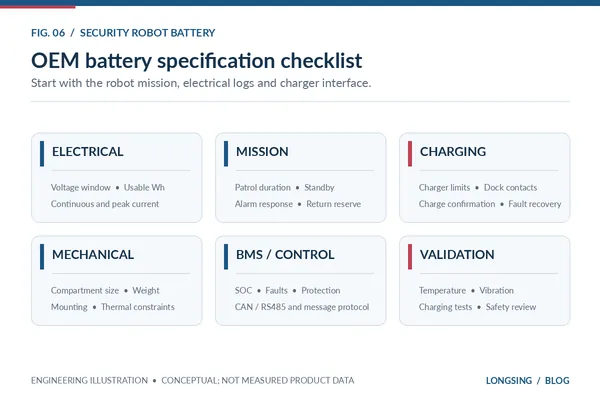
A security robot battery specification is easier to evaluate when it describes how the robot will be used. An OEM might begin with a nominal voltage and target capacity, but those figures alone do not establish a suitable pack design.
The supplier needs enough information to assess the energy requirement, electrical load, installation space and charging arrangement.
Security Robot Battery: OEM Design Checklist
| Design Area | Information to Provide |
|---|---|
| Electrical requirements | Nominal voltage and acceptable operating voltage range |
| Battery energy | Required usable energy, not only nominal Ah |
| Load profile | Measured average power, continuous current and peak current with duration |
| Patrol operation | Route duration, frequency and expected standby periods |
| Incident response | Additional load, mission duration and low-SOC operating requirements |
| Return-to-dock strategy | Return route, energy reserve and response to failed docking |
| Charging system | Charger specifications, charging current, dock interface and control signals |
| Battery installation | Compartment dimensions, maximum weight, mounting and connectors |
| Environment | Operating and charging temperature, vibration and enclosure conditions |
| Battery management | Required protection, monitoring, SOC reporting and fault information |
| Communication | Interface, higher-layer protocol, message definitions and timeout behavior |
| Qualification | Required testing, applicable safety requirements and compliance documentation |
The list should be refined during design review. Not every security robot needs the same communication functions, charging arrangement or environmental protection. A compact indoor unit that patrols smooth floors presents different mechanical and thermal requirements from an outdoor robot operating across ramps and uneven ground.
The expected charging frequency can also influence cell selection for the security robot battery. A robot that returns to its dock several times per day should be evaluated against a different cycling profile from one that completes a single patrol before overnight charging.
LONGSING rechargeable battery pack development
LONGSING provides rechargeable lithium battery cells and customized battery pack solutions for industrial applications, including mobile robotics. Its battery pack portfolio provides a starting point for discussing cell selection, pack configuration and project-specific integration requirements.
For a security robot project, useful initial materials include a measured power profile, battery compartment drawing, charger specification and the robot controller’s communication requirements. These allow the proposed pack to be assessed against the complete operating system rather than an isolated capacity target.
The final electrical ratings, BMS functions, mechanical configuration and validation requirements would be established during the OEM development process.
Conclusion
The most useful battery specification for a security robot begins with its patrol schedule and charging behavior.
A security robot battery must supply the energy required for routine surveillance, tolerate short periods of higher electrical demand and retain sufficient energy for the return journey. If the robot charges autonomously, docking contact, charger operation and fault recovery also affect whether it will be available for the next mission.
For OEM development, these requirements are best addressed together through a measured power budget, suitable cell selection and clearly defined interfaces between the battery, charger and robot controller.
LONGSING supports custom rechargeable lithium battery pack development for industrial robotics, with pack configuration and integration requirements evaluated according to the specific application.
Frequently Asked Questions About Security Robot Batteries
Click to explore more information about security robot battery design.
1. What type of battery is used in autonomous security robots?
Rechargeable lithium-ion and LiFePO4 battery packs are possible choices. The appropriate option depends on the robot’s voltage, energy requirement, peak current, size, weight, temperature range and charging schedule.
2. How do you calculate security robot battery runtime?
Start with the usable energy available from the battery in watt-hours. Divide that by the robot’s average electrical power for a preliminary estimate. For more accurate sizing, calculate energy consumption separately for patrol, standby, alarm response and return-to-dock operation.
3. Do cameras and onboard AI reduce battery runtime?
They consume energy and therefore contribute to the total power budget. The effect depends on the processor, camera configuration, data transmission and how long those systems remain active. Actual subsystem power should be measured when possible.
4. How does an autonomous security robot charge itself?
Where supported, the robot navigates to a charging station, aligns with the docking interface and establishes an electrical connection. Its charging system then verifies the required conditions and initiates charging. The specific process depends on the docking hardware and charger architecture.
5. How much battery should a security robot reserve for returning to its dock?
The reserve should be calculated from the expected return route, possible navigation delays, battery condition and operating environment. A fixed percentage cannot be recommended for every robot. The final threshold should be verified through mission testing.
6. Are 21700 lithium-ion cells suitable for security patrol robots?
They can be suitable when their electrical characteristics and physical dimensions meet the application requirements. A 21700-based pack should be evaluated for usable energy, current capability, installation space, weight and thermal design.
7. What does a smart BMS do in a security robot?
A suitable BMS monitors battery conditions and provides protective functions. Depending on the design, it may also report SOC, temperature, warnings and charging information to the robot controller, supporting patrol scheduling and fault handling.
8. What information does a battery manufacturer need for a custom security robot pack?
The OEM should provide the required voltage range, usable energy, average and peak loads, patrol schedule, charging method, available space, operating temperature and communication requirements. Return-to-dock behavior and applicable safety requirements should also be specified.
References
[2] Knightscope. How the K5 Robot Patrols Without Human Help. April 15, 2025. ↵
[3] Open Navigation LLC / Nav2. Using Docking Server. Nav2 Documentation, undated. ↵