Grid networks face severe instability due to intermittent renewable energy integration, causing costly power curtailment[1] and voltage fluctuations.
Without robust localized stabilization infrastructure, utility networks risk frequent blackouts and massive financial operational losses. Implementing an advanced, heavy-duty containerized energy storage system offers the ideal engineering answer to stabilize high-voltage transmission networks.
A grid-tied storage system manages transmission loads by charging during off-peak periods and discharging during peak demand hours.
This setup protects electrical assets, provides reliable frequency regulation, and balances total power distribution. By combining industrial lithium iron phosphate battery strings with advanced power conversion systems, utility operators achieve immediate active power control, ensuring full regional compliance and enhanced grid resilience.
The real value appears when engineering choices match the grid connection, because system size, cooling method, and protection architecture determine both performance and lifetime.
Table of Contents
- What is a BESS Container??
- How to Size a Battery Energy Storage System for a Utility Project?
- Is a BESS worth it?
1. What is a BESS Container?
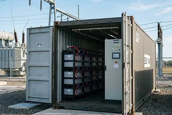
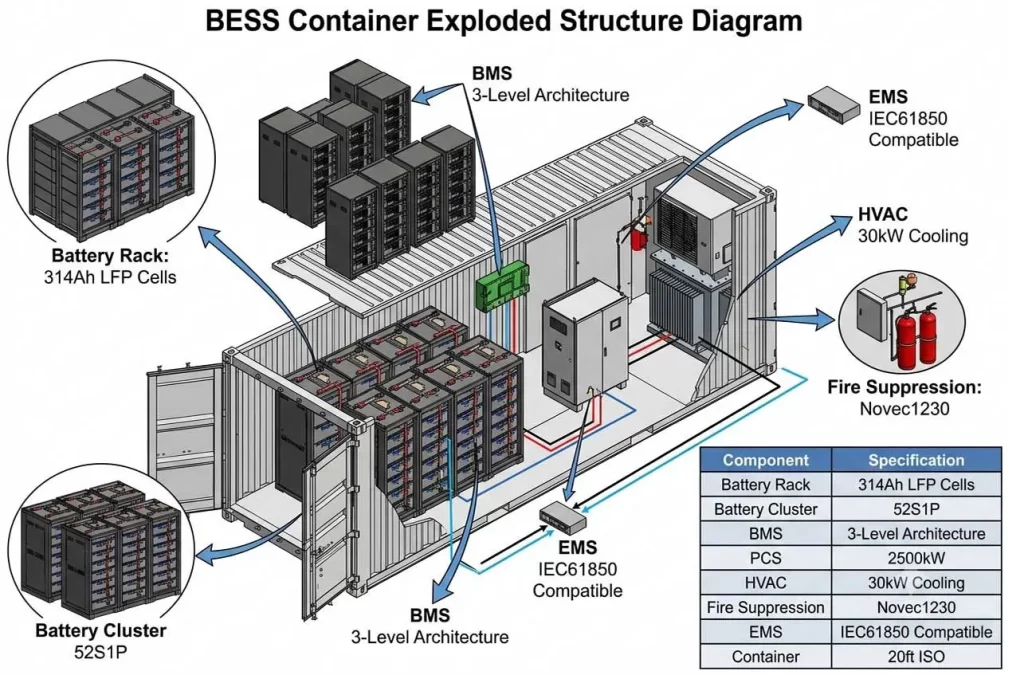
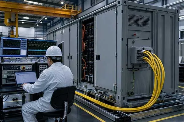
A BESS container is a factory-integrated energy storage enclosure that typically includes battery racks, BMS, PCS, HVAC or liquid cooling[2], fire suppression, auxiliary power, and monitoring hardware.
In utility and substation use, it is usually a containerized battery energy storage system designed for fast deployment and standardized grid connection.
How does a battery energy storage system work?
A battery energy storage system works by charging cells through a PCS during surplus power conditions and discharging through the same conversion path when the grid needs support.
In AC coupling[3], the PCS converts battery DC to AC near the container, while DC coupling keeps the battery tied more directly to a shared DC bus, which can improve system architecture efficiency in certain hybrid projects.
For utility sites, the battery energy storage system container often feeds a medium-voltage bus through transformer and switchgear stages, then reports status to SCADA[4] and EMS for control and dispatch.
Grid connection path
A practical substation layout usually follows this sequence: battery racks, BMS, PCS, low-voltage cabinet, transformer, MV switchgear, then grid interconnection. The transformer raises voltage to the substation side, and switchgear provides isolation, protection, and fault clearing so the battery energy storage system containers substation interface stays controllable under abnormal grid events.
That architecture is why a BESS container substation design is more than a battery box; it is a coordinated electrical plant.
Direct substation integration
Utilities connect a BESS container through MV switchgear or a substation transformer bank to keep current manageable and to meet protection requirements. A grid-connected battery energy storage system and battery energy storage substation configuration also depends on relay settings, grounding, and communications with the utility protection scheme.
In practice, the safest route is to treat the BESS substation as a power-system project, not only an equipment procurement project.
Why Utilities Are Deploying BESS at Substations?
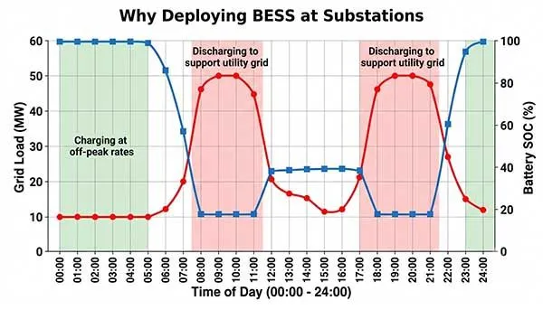
Utilities deploy battery storage substation assets because they can respond quickly, stabilize voltage and frequency, and reduce stress on congested feeders.
A utility-scale BESS can shave peaks, absorb renewable fluctuations, and provide fast grid support services that are difficult for conventional assets to match. The result is not only operational flexibility but also deferred network upgrades in many cases.
Operational value
For substations, the battery energy storage system container works best when the utility wants local flexibility rather than distant bulk energy.
Peak shaving lowers transformer loading, frequency regulation improves system balance, renewable integration reduces curtailment, and grid support helps maintain power quality during disturbances. A BESS for utility substations is therefore usually justified by multiple stacked services rather than one isolated revenue stream.
Commercial implication
From a commercial view, an integrated BESS container can unlock revenue or savings from energy shifting, ancillary services, and avoided infrastructure spending.
The strongest cases usually appear where congestion, demand charges, or renewable variability are already expensive, because the battery storage substation then becomes a control asset with economic value. This is why many developers now ask for a prefabricated energy storage enclosure instead of a custom civil-built station.
Turn Grid Constraints Into Value
Capture peak shaving, regulation, and support revenue
2. How to Size a Battery Energy Storage System for a Utility Project?
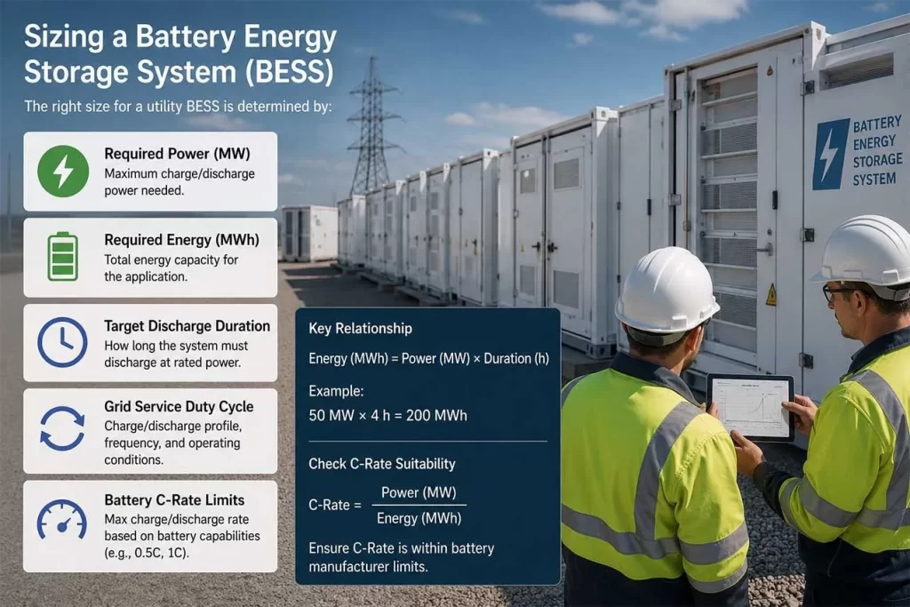
The right size for a utility BESS is determined by required power in MW, required energy in MWh, target discharge duration, grid service duty cycle, and battery C-rate limits. In most projects, the best container size is the one that matches the service profile, interconnection limit, and operating temperature range rather than the largest available enclosure.
Sizing logic
Power rating answers how much grid support the system can deliver at one moment, while energy rating answers how long it can sustain that output.
Duration selection often drives economics more than the battery nameplate[5], because a 1 MW/1 MWh system and a 1 MW/4 MWh system solve different problems even if both use a battery energy storage system container. C-rate selection matters because a higher C-rate can improve dispatch flexibility, but it can also increase thermal stress and accelerate degradation.
20ft and 40ft technical view
Below is a practical utility-facing reference for container planning, using market examples and standard industry layouts. The exact values vary by chemistry, thermal design, and regulatory target, but these ranges help teams compare a 20ft BESS container and a 40ft BESS container before detailed engineering begins.
| Parameter | 20ft Standard BESS Container | 40ft High-Density BESS Container |
|---|---|---|
| Battery Chemistry | Lithium Iron Phosphate (LFP) | Lithium Iron Phosphate (LFP) |
| System Capacity | 1.5 MW / 3.0 MWh | 3.44 MW / 6.88 MWh |
| Nominal Voltage | 1140 V DC | 1500 V DC |
| C-Rate Options | 0.5C (Energy) / 1C (Fast Response) | 0.5C (Optimized for Peak Shaving) |
| Cooling Method | Liquid Cooling (Chiller integrated) | Advanced Liquid Cooling with Smart HVAC |
| Round Trip Efficiency (RTE) | ≥ 88% (AC-to-AC) | ≥ 89.5% (AC-to-AC) |
| Design Lifespan | 6000 cycles @ 80% DOD | 6500 cycles @ 80% DOD |
| Compliance references | IEEE, UL 9540, UL 9540A, UL 1973, NFPA 855, IEC 62933, IEC 62619 | IEEE, UL 9540, UL 9540A, UL 1973, NFPA 855, IEC 62933, IEC 62619 |
Tips
In substation financial modeling, a 2% loss in Round-Trip Efficiency due to poor HVAC or transformer efficiency can cost over $150,000 in lost energy arbitrage value over a 10-year project lifecycle.
How to select the right size
The right size starts with the service objective, then moves to network constraints, not the other way around. If the project mainly does peak shaving, a shorter-duration system can be enough, but if it supports renewable smoothing[6] or congestion relief[7], the project may need more MWh and a more conservative C-rate.
The 5mwh bess container class is attractive for utility-scale deployment, yet it only fits the site when transport, foundation load, transformer capacity, and fire separation all align.
Liquid or air cooling
Liquid cooling is usually the better choice for high-density utility systems because it keeps cell temperatures more uniform and supports higher duty cycles.
Air cooling can still work for smaller or less demanding sites, but it often becomes less attractive when power density, ambient heat, and container lifetime matter more.
For an LFP battery energy storage system, thermal stability still depends on the whole design, not chemistry alone.
Typical applications
- Utility-Scale Solar Farms: Energy shifting, ramp-rate control, and grid export optimization.
- Wind Farms: Output smoothing and frequency response services.
- Utility Substations: Voltage support, spinning reserve replacement, and grid congestion relief.
- Industrial Manufacturing Plants: Peak demand reduction and backup power.
- Large EV Charging Stations: Reducing transformer upgrades and supporting ultra-fast charging.
- Data Centers: Battery-based UPS and power quality enhancement.
- Telecom Networks: Long-duration backup for 4G/5G infrastructure.
- Remote Microgrids: Integration with solar, wind, diesel generators, and energy management systems.
In many projects, the same containerized energy storage system can do more than one service if the controller strategy is designed well.
Common Failure Modes in Substation BESS Projects
The most common failure modes in substation BESS projects are thermal management faults, PCS faults, HVAC breakdown, transformer overload, and EMS communication loss. Good design reduces these risks through temperature control, protection coordination, conservative loading, and clear fault response logic.
Thermal and electrical risks
Thermal runaway is the most serious battery-side hazard, and it is usually made worse by poor thermal balance, weak fire detection, or delayed shutdown logic. PCS failure often shows up as lost availability, while HVAC failure can slowly degrade cells before operators notice the problem. These issues matter more in a battery storage substation because the utility expects predictable response under stress, not only nominal operation.
Control and interconnection risks
Transformer overload can happen when dispatch assumptions exceed real site limits or when ambient conditions reduce cooling margin. EMS communication failure[8] is equally important because the containerized battery energy storage system relies on signals from SCADA, PPC[9], and BMS to stay within safe operating boundaries. A robust substation battery storage system should therefore include alarms, fallback modes, and clear isolation rules.
Engineering discipline
The best projects combine protection studies, thermal studies, and communications testing before field energization. That is especially true for an MV substation integrated BESS, where the grid interface can expose the system to faults that a standalone commercial installation never sees. In practice, most reliability gains come from disciplined integration work rather than from adding more hardware.
Case Study: Solving High-Temperature Challenges for a 5MWh Containerized BESS at a 33kV Distribution Substation in Australia
Project Background
In early 2025, an Australian solar farm developer contacted Long Sing Energy regarding a utility-scale battery energy storage project planned for a remote solar farm in Western Australia.
The customer intended to install a 5MWh containerized Battery Energy Storage System (BESS) connected to a 33kV distribution substation. The primary objective was to improve renewable energy utilization, reduce solar curtailment, and provide peak shaving during evening demand periods.
During the initial discussions, the customer requested a battery system capable of delivering 230V AC output. Their engineering team originally planned to integrate the battery container directly with existing site loads while simultaneously supporting grid-connected operation.
After reviewing the project requirements, Long Sing Energy’s engineering team identified a major technical challenge. While 230V AC is suitable for auxiliary equipment and local facility loads, it is not appropriate as the primary output voltage for a utility-scale 5MWh BESS connected to a 33kV distribution network.
A redesign of the power architecture was required before the project could proceed.
Engineering Consultation and System Redesign
A series of technical meetings was organized involving the solar farm developer, EPC contractor, electrical consultants, and Long Sing Energy engineers.
The original proposal consisted of a low-voltage output architecture that would have resulted in excessive current, larger cable sizes, higher energy losses, and reduced system efficiency.
After completing the load flow analysis and grid interconnection review, Long Sing Energy proposed a revised solution consisting of:
- 5MWh LFP battery system
- 1.25MW rated discharge power
- Four-hour storage duration
- 1250VDC battery architecture
- 690VAC PCS output
- 690V/33kV step-up transformer
- SCADA communication with utility control center
The revised design significantly reduced electrical losses while complying with local grid requirements.
Following technical approval, the customer issued a pilot purchase order for one complete 5MWh BESS container.
High-Temperature Environmental Challenge
One of the most critical concerns raised by the customer was ambient temperature.
Historical meteorological data showed summer temperatures reaching 45°C in the project area, with solar radiation causing container surface temperatures to exceed 60°C.
The customer requested evidence that the battery system could maintain stable operation under these extreme environmental conditions while continuously performing four-hour charge and discharge cycles.
To validate the design, Long Sing Energy conducted an extensive Factory Acceptance Test (FAT) program.
Factory Acceptance Testing
The first round of testing was performed under standard laboratory conditions.
- Ambient temperature: 25°C
- Battery capacity retention: 100%
- Maximum cell temperature: 34.6°C
- Temperature difference between racks: 3.1°C
- Round-trip efficiency: 91.8%
All parameters met project requirements.
The engineering team then simulated Australian summer operating conditions inside a controlled environmental chamber. Ambient temperature was gradually increased to 45°C while maintaining a continuous four-hour discharge profile.
Several performance issues emerged during testing.
Maximum battery rack temperature reached 52.4°C. The temperature difference between the upper and lower battery racks increased to 11.2°C. HVAC power consumption increased by 28%.
Thermal imaging revealed significant heat accumulation in the upper rear section of the container.
Although the system remained operational, the results indicated a potential long-term degradation risk.
Failure Analysis
A detailed thermal investigation was performed using airflow mapping and CFD simulation.
The root cause was not the battery cells themselves. Instead, engineers discovered that the original air circulation design created a thermal dead zone near the upper battery racks.
As hot air accumulated, cooling efficiency decreased and temperature uniformity deteriorated.
If left unresolved, the projected consequences included accelerated battery aging, reduced cycle life, and increased maintenance costs over the system’s operational lifetime.
The analysis challenged a common industry assumption that battery cell selection is the primary determinant of BESS reliability.
In reality, thermal management design often has a greater impact on long-term system performance than cell chemistry alone.
Optimization Process
Long Sing Energy engineers redesigned the thermal management architecture.
Several improvements were implemented:
A dual-channel airflow structure was introduced. Additional return-air pathways were added to eliminate stagnant air pockets. HVAC control algorithms were optimized based on rack temperature feedback. Airflow balancing devices were installed throughout the container.
Following implementation, a second round of high-temperature testing was conducted under identical operating conditions.
Final Test Results
The optimized design delivered significant improvements.
Under 45°C ambient temperature:
Maximum rack temperature decreased from 52.4°C to 45.8°C. Temperature difference between racks decreased from 11.2°C to 2.9°C. HVAC energy consumption decreased by 17%. System round-trip efficiency improved from 89.4% to 91.1%. Projected battery degradation during the first ten years was reduced by approximately 18%.
The customer’s engineering consultants approved the revised design without further modifications.
Project Outcome
The successful completion of the testing program enabled the customer to proceed with full project deployment.
The final system architecture consisted of a 1250VDC LFP battery platform, integrated PCS, intelligent thermal management system, and 33kV grid interconnection package.
Beyond meeting the technical requirements, the project demonstrated the importance of system-level engineering in utility-scale battery storage applications.
Rather than focusing exclusively on battery cell specifications, the optimization of thermal management, airflow distribution, and power conversion architecture delivered measurable improvements in efficiency, reliability, and long-term project economics.
For utility-scale solar developers operating in high-temperature environments, these factors often determine project success more than battery chemistry alone.
Size for Duty Cycle, Not Guesswork
Align MW, MWh, and C-rate before procurement
3. Is a BESS worth it?
A BESS is worth it when stacked revenues or avoided costs exceed the installed cost, operation cost, and degradation cost over the project life. For utility substations, ROI depends on interconnection savings, deferred upgrades, ancillary service value, and how well the container is sized to the actual duty cycle.
ROI factors
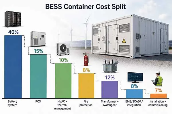
Cost studies show that utility-scale BESS pricing has fallen sharply, but the system still needs a realistic revenue model. The battery pack is only part of the project cost, because balance-of-system, interconnection, control, and substation works can be large cost drivers. That is why a battery energy storage substation should be evaluated as a whole asset, not as a battery price per kWh alone.
Simple ROI logic
A practical ROI calculation compares annual savings or revenue against annualized capital cost and operating cost. If the site avoids transformer upgrades, reduces peak demand charges, earns ancillary service revenue, or improves renewable capture, the economics strengthen quickly. A containerized energy storage system with the right duration and C-rate usually outperforms an oversized system that cycles poorly and ages faster.
Procurement view
For buyers, the core question is not whether a BESS is useful, but whether the delivered configuration matches the substation constraint. A battery energy storage system containers substation package can be cost-effective when the supplier provides factory integration, clear compliance documents, and verified interface data. At that point, the commercial case and the engineering case move in the same direction.
Maximize Your Substation ROI
Predictive degradation modeling guarantees >15-year operational lifecycle asset value.
Conclusion
Integrating high-capacity storage containers into substation networks represents a critical strategy for modern grid stabilization and renewable power integration. Selecting the correct enclosure dimensions, battery chemistry, and thermal management systems ensures optimal lifecycle performance and prevents catastrophic field failures.
While initial capital expenditure remains significant, multi-variable revenue stacking leads to attractive long-term investment returns. Project operators can secure grid reliability and maximize financial returns by collaborating with experienced manufacturing partners to deploy fully compliant, high-density energy storage systems.
Frequently Asked Questions
Click to explore more information about BESS Container Design
Q: What is battery storage?
A: Battery storage is a system that stores electrical energy in rechargeable batteries and releases it when needed. It helps balance supply and demand, improve grid reliability, and support renewable energy integration.
Q: What is a BESS in substation?
A: A Battery Energy Storage System (BESS) in a substation stores energy and provides services such as peak shaving, frequency regulation, voltage support, and backup power to improve grid stability.
Q: What is the difference between a battery and a BESS?
A: A battery is the energy storage device itself, while a BESS includes batteries, Battery Management System (BMS), Power Conversion System (PCS), Energy Management System (EMS), cooling, fire protection, and monitoring equipment.
Q: Is BESS AC or DC?
A: Batteries operate in DC, but most BESS installations use a PCS to convert DC power into AC power for grid or facility connection. Therefore, a BESS contains both DC and AC sections.
Q: How big is a BESS container?
A: Most utility-scale BESS containers are built in 20-foot or 40-foot ISO containers. A typical 20-foot container measures about 6.1m × 2.4m × 2.6m, while a 40-foot container is about 12.2m long.
Q: What is the capacity of a BESS container?
A: The capacity depends on battery chemistry and design. Modern lithium-ion BESS containers typically range from 1MWh to over 5MWh per container, with higher-density models continuing to emerge.
Q: What is the lifespan of a BESS?
A: A well-designed lithium-ion BESS generally lasts 10–20 years, depending on cycle frequency, operating temperature, depth of discharge, and maintenance practices.
Reference:
[1]Understand why power curtailment remains a major challenge for renewable projects.↪
[2]See how thermal management with HVAC cooling affects battery performance and lifespan.↪
[3]Compare AC and DC coupling architectures for energy storage projects.↪
[4]Explore how SCADA systems monitor and control utility assets.↪
[5]Discover the difference between nameplate and usable battery capacity.↪
[6]Explore how energy storage smooths renewable generation variability.↪
[7]Understand how storage reduces transmission congestion challenges.↪
[8]Understand how communication failures affect energy storage operations.↪
[9]Explore the role of PPC in renewable and storage facilities.↪