
A practical engineering framework for evaluating loads, autonomy, solar input, battery chemistry, and protection in unattended monitoring equipment.
Power interruption can leave unattended equipment blind, stop data transmission, and increase costly offshore maintenance. If the battery is sized from voltage and amp-hours alone, hidden peak loads or poor solar conditions may undermine the system. Accurate solar battery sizing connects the real load profile with autonomy, charging, environment, and verification.
Solar battery sizing for remote monitoring systems should account for daily energy consumption, peak loads, required days of autonomy, battery chemistry, usable depth of discharge, system efficiency, available solar charging, operating conditions, and maintenance intervals. Engineers must calculate continuous and intermittent loads separately, confirm the charging opportunity, and then validate the proposed battery and BMS against the real equipment profile rather than relying on a nominal voltage or capacity label.
The following method connects load calculation, battery autonomy, component selection, and an ocean buoy engineering example without assuming unavailable project data.
Table of Contents
- How Should Daily Power Demand Be Calculated for Remote Monitoring Systems?
- How Much Battery Capacity and Autonomy Does an Off-Grid Solar System Need?
- Which Battery Chemistry and Protection Design Are Suitable for Harsh Remote Environments?
- How Can Solar Battery Sizing Be Applied to an Ocean Monitoring Buoy Project?
1.How Should Daily Power Demand Be Calculated for Remote Monitoring Systems?
Daily demand should be calculated from each device’s power and operating time, with continuous, scheduled, nighttime, and intermittent loads listed separately.[1] For remote monitoring systems, average Wh/day is essential, but it is not sufficient: startup current, radio transmission, camera operation, and simultaneous device activity must also be measured so that the battery, wiring, connectors, BMS, and converter can tolerate peak demand.
Build an Equipment-Level Load Schedule
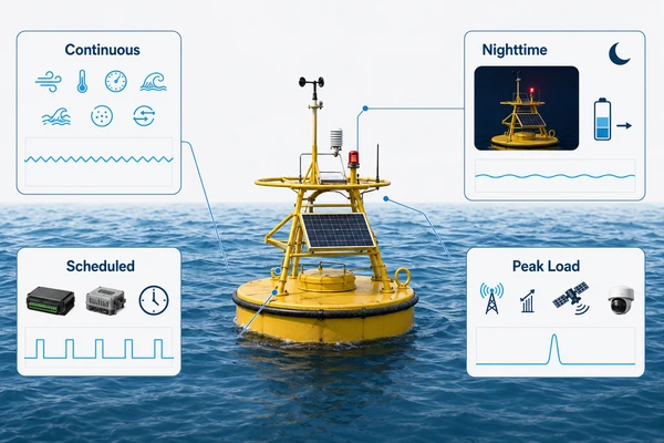
Start the solar battery sizing process with a complete electrical inventory. Record nominal voltage, measured or specified power, operating mode, duty cycle, start time, duration, and possible simultaneous operation. Continuous sensors belong in one group; scheduled sampling, data logging, communication windows, warning lights, heaters, pumps, and cameras belong in separate groups.
The basic solar battery sizing calculation is:
Daily Energy Consumption (Wh/day) = Σ Equipment Power (W) × Daily Operating Time (h)
For duty-cycled equipment, use the energy of each active and standby state. Conversion losses should not be hidden inside estimated device power; document DC/DC converters, inverters, cable losses, and controller consumption separately. This gives a traceable battery sizing calculation for a solar-powered monitoring equipment platform.
| Load category | Typical operating pattern | Required engineering input | Primary design effect |
|---|---|---|---|
| Continuous | Always active | Measured steady power | Baseline Wh/day |
| Scheduled | Timed sampling or transmission | Power, frequency, and duration | Daily energy and overlap |
| Nighttime | Active without solar input | Hours per night and seasonal variation | Overnight battery reserve |
| Intermittent peak | Startup, radio, or video burst | Peak current and pulse duration | BMS, cell, cable, and connector rating |
Separate Energy Demand from Power Demand
Communication equipment can have modest average consumption while producing short current pulses. Video transmission may add both sustained energy and higher peaks, especially when compression, illumination, and wireless links operate together. Therefore, solar battery sizing must pass two checks: the energy check in Wh/day and the power check in watts or amperes. A remote IoT power system can meet one and still fail the other.
2.How Much Battery Capacity and Autonomy Does an Off-Grid Solar System Need?
An off-grid solar battery system needs enough usable energy to support the verified daily load through the required low-solar period, with allowances for depth of discharge, efficiency, temperature, aging, and project reserve. Battery autonomy should be defined from the site’s weather risk and acceptable service interruption—not selected as a generic number—and then checked against the solar array’s realistic energy recovery capability.
Convert Daily Demand into Nominal Battery Energy
Once the load schedule is confirmed, use:
Required Nominal Battery Energy (Wh) = Daily Energy Consumption × Required Days of Autonomy ÷ Usable Depth of Discharge ÷ System Efficiency
Required Battery Capacity (Ah) = Required Nominal Battery Energy (Wh) ÷ Nominal System Voltage (V)[2]
The usable depth of discharge depends on chemistry, service-life target, operating temperature, and manufacturer limits. System efficiency should reflect the complete discharge path. In solar battery sizing, capacity margin may also be needed for aging, production tolerance, uncertain duty cycles, and the maintenance interval, but each margin should be documented rather than stacked without justification.
No final solar battery sizing result should be calculated until the actual load list, duty cycles, peak currents, autonomy target, system voltage, temperature range, and efficiency assumptions are available.
Check Whether Solar Input Can Restore the Reserve
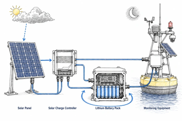
In solar battery sizing, capacity only bridges an energy deficit; it does not correct an undersized charging source. Estimate solar availability with:
Estimated Daily Solar Energy (Wh/day) = Solar Panel Rated Power (W) × Peak Sun Hours × System Derating Factor
Peak sun hours must reflect location and season. The derating factor should consider panel temperature, orientation, contamination, shading, cable loss, and controller conversion. Solar battery sizing should compare energy generation with both daily consumption and the extra energy required to recover after several low-sunlight days.
The solar charge controller must match the battery chemistry, series count, charge-voltage limit, maximum charging current, and temperature strategy. For an off-grid solar battery system, recovery time can be as important as the nominal days of autonomy because another poor-weather period may arrive before the battery is fully replenished.
Define Autonomy as an Operating Requirement
Battery autonomy should be tied to weather data, mission criticality, access difficulty, and maintenance response time.[3] Engineers should distinguish minimum survival operation from full-feature operation: for example, a controller may preserve critical sensing and communication while deferring nonessential video activity. Such load management must be intentionally designed and verified; it should not be assumed during solar battery sizing.
3.Which Battery Chemistry and Protection Design Are Suitable for Harsh Remote Environments?
The suitable chemistry is the one that meets energy density, power, temperature, service-life, safety, space, and maintenance requirements after system-level testing. A marine lithium battery also needs a correctly configured BMS, consistent cells, reliable insulation and connectors, and an enclosure strategy appropriate to the installation. Chemistry selection alone cannot ensure dependable operation in a harsh marine environment.
Compare Chemistry at System Level
NMC lithium-ion cells can suit compact installations requiring relatively high energy density, while LiFePO4 may be preferred where cycle life, thermal behavior, or a different voltage platform carries more weight.[4] The choice depends on the confirmed operating profile. Cell format also matters: a 21700 battery pack may support a modular custom lithium battery pack design, but parallel count, thermal paths, mechanical restraint, current sharing, and replacement strategy must be engineered.
For any marine lithium battery, compare more than nameplate capacity. Review allowable charge and discharge temperatures, continuous and pulse current, voltage window, storage behavior, cell variability, expected calendar life, and the effect of partial state of charge. These inputs influence usable energy and solar battery sizing.
Coordinate the BMS with Cells and Loads
A marine battery BMS should provide overcharge, over-discharge, overcurrent, short-circuit, and temperature protection.[5] It should also support voltage and temperature monitoring, an appropriate balancing strategy, and fault behavior compatible with the mission. Protection thresholds and delays must match the selected cells and expected peak loads; otherwise legitimate communication bursts could cause shutdown, or harmful conditions might not be interrupted promptly.
Cell OCV, internal resistance, and capacity grading help reduce imbalance. Temperature sensors must be placed where they can detect relevant cell or connection heating. Insulation, fusing where applicable, creepage and clearance, wiring restraint, connector sealing, enclosure drainage or pressure management, waterproofing, and corrosion resistance should be evaluated together. These measures turn a cell assembly into a more dependable off-grid solar battery system.
4.How Can Solar Battery Sizing Be Applied to an Ocean Monitoring Buoy Project?
For an ocean monitoring buoy, solar battery sizing begins by mapping every sensor, communication device, warning light, and camera to its operating schedule and peak current. The proposed battery can then be checked against low-sunlight autonomy, solar recovery, charging limits, environmental protection, and maintenance access. Without verified loads and site solar data, a 3S20P, 100Ah proposal cannot by itself prove system suitability.
Project-Based Engineering Analysis
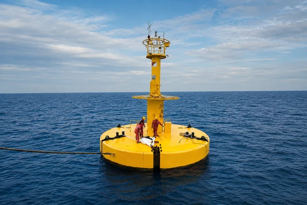
This engineering example concerns a long-term, unattended buoy in the South China Sea for marine environmental monitoring. Loads include wind speed and direction, atmospheric pressure, temperature, humidity, visibility, precipitation, wave height, tide level, seawater temperature, salinity, and ocean current sensors. It also supports 4G, CAT.1, and BeiDou communication, a marine navigation warning light, and video-monitoring equipment.
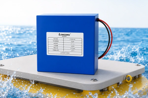
The data buoy power system can support typhoon, storm-surge, and large-wave warning; maritime visibility and current monitoring; ecological observation; fisheries; and offshore wind projects. Its proposed energy architecture combines solar generation with a 21700 NMC, 3S20P, 100Ah, 12V-class battery system.
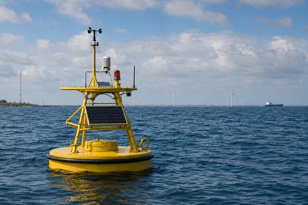
The “12V 100Ah lithium battery” description is a system-class label, not an exact energy value.[6] A typical 3S NMC pack may be approximately 10.8V or 11.1V nominal and approximately 12.6V at maximum charge, depending on the selected cell specification. Final nominal energy must use the confirmed cell capacity and nominal voltage; it should not automatically be reported as 1.2kWh.
Load and Weather Conditions That Control the Design
Continuous sensing establishes the baseline. Scheduled measurements and transmissions add duty-cycled demand. The warning light is an important nighttime load because it operates when solar generation is unavailable. Video monitoring and wireless communication can increase both daily energy and instantaneous current, particularly during simultaneous transmission. Their actual consumption and peak current must come from specifications and measurement.
Cloud, monsoon conditions, typhoons, contamination, and wave-driven changes in panel orientation may reduce solar charging. The required days of autonomy and recovery time therefore need project-specific solar data and an agreed operating strategy. A solar charge controller must match NMC charging limits and the confirmed 3S pack specification.
An illustrative solar battery sizing risk—not a reported field failure—is that average-load estimates could overlook communication and video peaks while several low-sunlight days reduce state of charge. Other plausible risks include controller mismatch, cell imbalance, water ingress, connector corrosion, and abnormal connection temperature. Retrieval difficulty and long maintenance intervals raise the value of conservative validation, reliable connectors, insulation, waterproofing, corrosion control, and serviceable enclosure design in an ocean monitoring buoy.
Verification and Pack Production Workflow
Before freezing the design, review the complete equipment list; measure continuous and peak current; verify Wh/day; and test communication overlap, nighttime demand, and simulated low-sunlight battery autonomy.[7] Battery verification should include cell OCV, internal resistance, capacity and consistency grading, pack voltage, charge/discharge behavior, BMS protections, temperature monitoring, and solar-charging compatibility. Inspect connectors and insulation, and perform waterproofing or salt-spray/corrosion verification when the project requires it. Test conditions and acceptance limits must be agreed rather than invented.
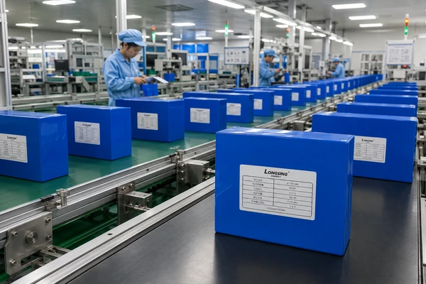
A relevant production flow is cell inspection; OCV and internal-resistance grading; capacity matching; 3S20P configuration; cell connection and welding; insulation and structural protection; BMS integration; wiring and connector installation; enclosure assembly; functional inspection; charge/discharge verification; and final quality inspection. This sequence supports traceability, but the finished marine lithium battery still requires validation against the actual buoy load profile and installation environment.
Conclusion
Remote monitoring systems should not select a battery from voltage or amp-hour capacity alone. Reliable solar battery sizing integrates the actual load profile, communication peaks, charging conditions, required autonomy, operating environment, maintenance interval, and test results. Final design validation must use confirmed solar conditions, temperature, charging method, service-life target, and equipment schedule.
LONGSINGX can discuss your monitoring equipment, load profile, installation environment, and custom battery-pack requirements to help define an appropriate engineering and sample-testing plan.
Frequently Asked Questions
Click to explore more information about Solar Battery Sizing for Remote Monitoring Systems
Q: How do you size a solar battery for a remote monitoring system?
A: Start by calculating the daily energy consumption of every sensor, communication device, warning light, camera, controller, and auxiliary component. The calculation must also consider peak loads, required days of autonomy, usable depth of discharge, system efficiency, available solar charging, operating temperature, maintenance intervals, and battery aging. The final design should be validated using the equipment’s actual load profile.
Q: How is daily energy consumption calculated?
A: Daily energy consumption is calculated using the formula: Daily Energy Consumption (Wh/day) = Σ Equipment Power (W) × Daily Operating Time (h). Continuous sensors, scheduled measurements, nighttime equipment, communication transmissions, and video-monitoring loads should be calculated separately before being combined. Standby consumption and conversion losses should also be included where applicable.
Q: What is the difference between battery capacity in Wh and Ah?
A: Watt-hours measure the total energy stored in a battery, while amp-hours describe electrical charge at a particular voltage. Required battery capacity in Ah can be calculated by dividing the required nominal battery energy in Wh by the battery’s nominal system voltage. Because Ah values cannot be compared accurately without considering voltage, Wh is generally more useful when evaluating total system energy.
Q: How many days of battery autonomy does an off-grid monitoring system need?
A: There is no universal number of autonomy days suitable for every project. The requirement depends on local weather, seasonal solar availability, system criticality, acceptable downtime, maintenance response time, and the difficulty of accessing the equipment. Offshore or unattended systems may require additional reserve because several cloudy or low-sunlight days can occur before normal solar charging resumes.
Q: Why must communication and video peak loads be considered?
A: Wireless communication modules and video-monitoring equipment may draw short but substantial current peaks during startup, data transmission, image processing, or simultaneous operation. These peaks may not significantly change the average daily energy calculation, but they can trigger BMS protection or cause voltage drop if the cells, wiring, connectors, or converters are not correctly rated.
Q: Is a 3S NMC lithium-ion battery exactly 12V?
A: No. A 3S NMC battery is normally described as a 12V-class battery system, but its exact voltage depends on the selected cell specification. A typical 3S NMC pack may have a nominal voltage of approximately 10.8V or 11.1V and a maximum charging voltage of approximately 12.6V. The battery energy must therefore be calculated using the confirmed nominal voltage and actual cell capacity.
Q: What BMS protection does a marine lithium battery need?
A: A marine battery BMS should normally provide overcharge, over-discharge, overcurrent, short-circuit, and temperature protection. It should also monitor cell-group voltage and pack temperature and use a suitable balancing strategy. Protection thresholds, delay times, and current ratings must match the selected cells, solar charge controller, communication peaks, and actual equipment load profile.
Q: Is a 3S20P 100Ah battery suitable for an ocean monitoring buoy?
A: A 3S20P, 100Ah, 12V-class battery may be evaluated as a proposed solution, but capacity and configuration alone cannot confirm suitability. Engineers must verify the buoy’s complete load list, daily energy consumption, communication and video peak currents, required autonomy, solar conditions, charging method, temperature range, marine environment, maintenance interval, and service-life target before approving the final battery design.
Reference: