
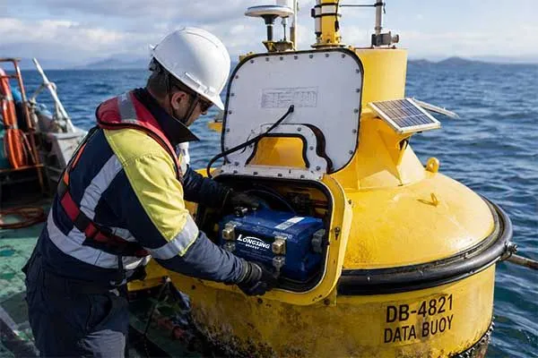
A data buoy that goes dark mid-mission wastes the deployment budget along with the data behind it. Vessel time, sensor calibration, and weeks of monitoring disappear the moment the power system fails.
The fix starts with one component: a properly engineered marine data buoy system battery, matched to the mission from day one rather than bolted on afterward.
A marine data buoy system battery is the power source, charge controller, and battery management circuit that keep a data buoy running between service visits.
Most systems pair a solar panel with a rechargeable pack — commonly LiFePO4 — sized to cover sensor load, communication load, and a reserve margin through low-sunlight periods. Primary lithium cells such as Li-SOCl2 serve buoys with no solar input at all.
The engineering answer for a marine data buoy system battery lies in sizing, chemistry, and a tested install-and-maintenance process, covered next with real specifications.
Table of Contents
- What Is a Data Buoy Battery System?
- How to Select a Data Buoy Battery?
- Step-by-Step Battery Replacement & Maintenance Protocol
What Is a Data Buoy Battery System?
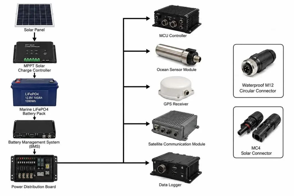
A data buoy battery system is the complete power chain — battery pack, charge controller, wiring harness, and connector interface — installed inside a buoy hull to run sensors, GPS, and telemetry[1] continuously.
The system stores energy harvested from a solar array or wind generator and releases it on demand, holding voltage steady even when a satellite modem draws a short current spike.
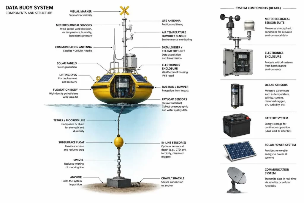
Buoy platforms vary in mission and hull design, and the variation matters for power planning.
A weather buoy reporting meteorological buoys data every ten minutes draws a different load profile than a wave buoy measuring sea state, and both differ again from a fixed platform running an AtoN navigation light to mark Aids to Navigation for maritime safety.
A metocean buoy combining wind, wave, and current channels stacks several oceanographic sensor inputs onto one power bus, while a subsea beacon below the surface has no solar access and relies entirely on primary cells.
A solar powered data buoy carrying only a GPS and telemetry radio needs far less reserve than a metocean buoy running continuous oceanographic monitoring, and a nearshore platform using solar powered buoy lights adds its own predictable evening load.
Bouys deployed in warm tropical water face faster connector corrosion than those in temperate seas. Despite these differences, every configuration is, at its core, a marine data buoy system battery application sized to the worst week of the deployment, not the average day.
Power Consumption of Typical Data Buoys
A typical data buoy power system architecture stacks four layers: solar or wind harvesting, a charge controller (MPPT for higher-voltage arrays, PWM[2] for smaller panels), the battery bank, and a load bus feeding the GPS, satellite modem, sensor suite, and onboard controller.
| Subsystem | Typical Current Draw | Duty Cycle |
|---|---|---|
| GPS receiver | 15–40 mA | Continuous or duty-cycled |
| Satellite modem (Iridium/Argos) | 200–500 mA transmit / 3–8 mA idle | Seconds per hour |
| Sensor suite | 10–150 mA | Sampling-interval dependent |
| Onboard controller / logger | 5–20 mA | Continuous |
| AtoN navigation light | 20–100 mA (LED, flashing) | Dusk-to-dawn |
| Sleep-mode baseline | 0.5–2 mA | Between wake cycles |
Waterproof connector interfaces — usually a bulkhead-mounted MCBH or Subconn-style plug — separate the battery compartment from the electronics bay, letting a technician swap a pack without opening the sealed hull.
Data buoy controllers manage sleep-mode logic, and this firmware tuning is the single largest lever over daily consumption. A buoy monitoring system should be sized against worst-case load, not average load, because a satellite uplink or a signal light can draw several times the idle current for a few seconds at a time. This layered design is common to nearly every marine data buoy system battery installation, regardless of hull size.
Designed for Long-Term Offshore Deployment?
Get matched LiFePO4 packs sized for your buoy power budget.
How to Select a Data Buoy Battery?
Selecting a marine data buoy system battery — typically packaged as a data buoy battery pack — starts with mission duration, then works through sensor load, communication load, available solar resource, deployment latitude[3], and required reserve days before landing on a chemistry and a specific capacity.
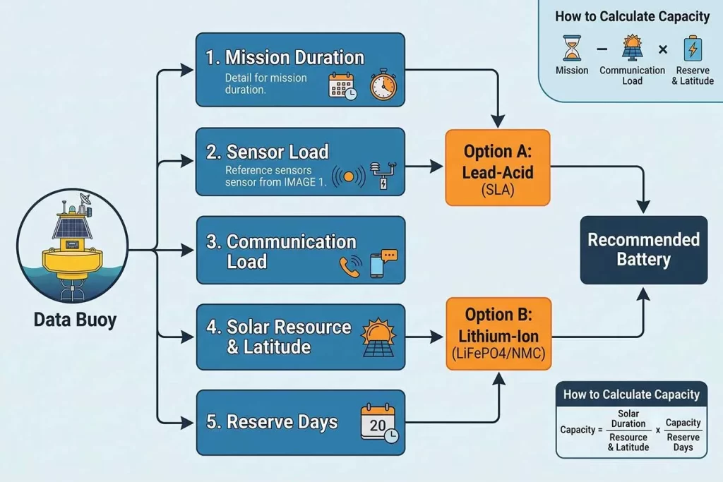
LiFePO4 fits most solar-charged missions; Li-SOCl2 fits low-power sensors with no solar access; SLA suits short, low-cost deployments; NMC suits weight-sensitive platforms. The output of this chain is a capacity figure in amp-hours, not a battery model number.
The selection chain runs in one direction.
Mission duration sets the floor — a 30-day pilot and a 3-year permanent mooring do not share a battery strategy. Sensor load and communication load stack on top, since a sea buoy carrying a full sensor array and a satellite modem draws far more current than a sea buoy that only logs GPS position.
Solar resource and latitude then determine how much of that load a panel can realistically replace across the darkest month of the year, not the sunniest one. Hybrid solar-wind systems close this gap at high latitudes, where winter solar input alone cannot carry the reserve.
Reserve days[4] set the chemistry and the final capacity of the marine data buoy system battery: an ocean monitoring battery for a metocean buoy differs from a weather buoy battery for a coastal platform mainly in reserve days and connector rating. A data buoy controllers board that manages this chain in firmware can cut required battery size by 20–40% versus a marine buoy battery left running continuously, and a sea buoy sized this way rarely runs short of reserve.
How to calculate battery capacity:
Required capacity (Ah) = (Average daily load in Ah × Reserve days) ÷ (Depth of discharge × Temperature derating factor)
A buoy drawing 0.4 Ah per day, needing 10 reserve days, and running a LiFePO4 pack at 80% depth of discharge with a 0.9 temperature derating factor needs roughly (0.4 × 10) ÷ (0.8 × 0.9) ≈ 5.6 Ah of usable capacity for the marine data buoy system battery — the pack is then sized up to the next standard configuration to leave working margin.
Battery Chemistry Comparison
Chemistry choice for a marine buoy battery is rarely about raw energy density alone; cycle life, self-discharge, and safety inside a sealed hull all weigh into the decision.
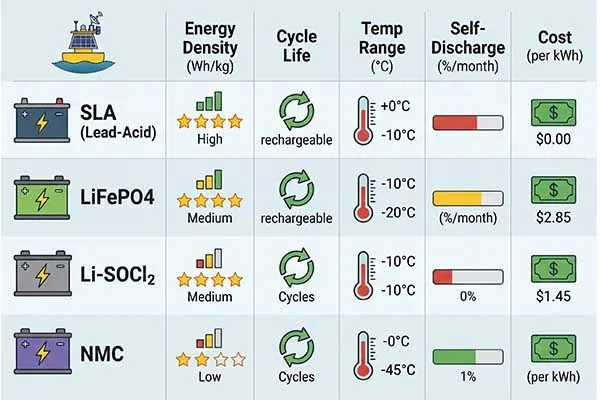
SLA remains common on short, budget-driven deployments, even though cycle life and cold-weather performance lag behind lithium options. LiFePO4 has become the default recommendation for a solar-charged marine data buoy system battery because it tolerates partial-state-of-charge cycling, holds a stable voltage under load, and carries a lower thermal-runaway risk than other lithium chemistries.
Can I upgrade my SLA buoy system to Lithium?
Yes. Most SLA buoy systems can be upgraded to LiFePO₄ batteries with a compatible charger and battery management system (BMS). This upgrade reduces weight, extends service life, improves efficiency, and lowers maintenance requirements. Contact our LiFePO4 Battery Expert for free.
Li-SOCl2 primary cells serve buoys with no solar input, delivering very low self-discharge over multi-year deployments but no rechargeability. NMC delivers the highest energy density of the four and suits weight-sensitive hulls, though a marine data buoy system battery built on NMC demands a more conservative safety margin and a more capable battery management system than LiFePO4.
| Chemistry | Nominal Voltage | Cycle Life | Energy Density | Typical Use |
|---|---|---|---|---|
| SLA | 12V | 200–500 cycles | 30–40 Wh/kg | Short, low-cost deployments |
| LiFePO4 | 12.8V / 25.6V | 2,000–4,000 cycles | 100–160 Wh/kg | Solar-charged, long-term buoys |
| Li-SOCl2 | 3.6V (primary) | Non-rechargeable | 400–700 Wh/kg | Sensors with no solar input |
| NMC | 11.1V / 14.8V | 500–1,000 cycles | 150–220 Wh/kg | Weight-sensitive, compact hulls |
Safety warning: Never mix battery chemistries, cell ages, or capacities within the same battery bank, and never attempt to recharge Li-SOCl2 primary cells — doing so can cause venting, fire, or explosion inside a sealed hull. Confirm polarity at the connector interface before every reconnection, and always disconnect the load bus before disconnecting the battery.
Battery Life Prediction
Battery life prediction combines average current, peak current, and sleep current against the solar input the site can realistically deliver.
Average current sets the baseline daily drain; peak current — drawn for seconds during a satellite uplink or a sensor burst — matters mainly for wire gauge and connector rating rather than total capacity. Sleep current, often under 1 mA, becomes the dominant term on buoys that spend most of the day idle between transmissions.
Solar input is not fixed: seasonal variation cuts effective panel output by 40–70% between summer and winter at mid and high latitudes, and biofouling[5] on the panel surface quietly erodes output over a multi-month deployment.
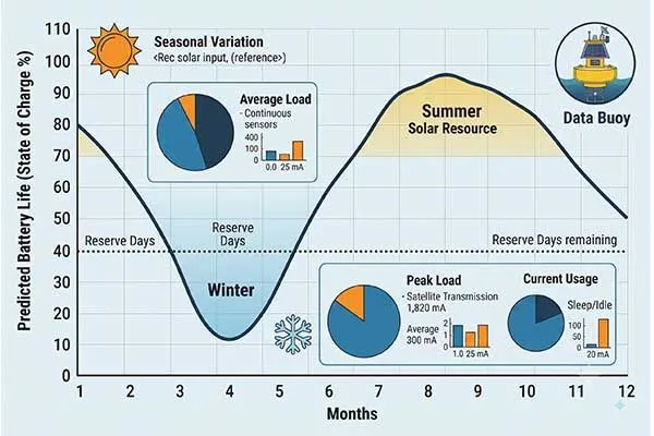
Reserve days close the loop, converting the gap between worst-case load and worst-case solar input into a minimum usable capacity, and a well-documented buoy monitoring system keeps this figure auditable across an entire fleet of bouys.
Power Budget Example
A representative power budget example for a mid-size marine buoy battery serving a data buoy power system shows how the pieces stack.
GPS logging every ten minutes, a satellite modem transmitting hourly, a sensor suite sampling every fifteen minutes, and an onboard controller running continuously combine into a daily energy draw that solar input must offset, with the shortfall covered by the battery.
| Load | Current Draw | Duty Cycle | Daily Ah |
|---|---|---|---|
| GPS | 25 mA | Continuous | 0.60 |
| Satellite modem | 350 mA (tx) / 5 mA (idle) | 10 sec/hour | 0.09 |
| Sensor suite | 60 mA | 2 min every 15 min | 0.16 |
| Controller / logger | 8 mA | Continuous | 0.19 |
| Idle / sleep baseline | 0.8 mA | Remaining time | 0.02 |
| Total consumption | — | — | ≈1.06 Ah |
Total consumption of roughly 1.06 Ah per day, carried through a 10-day reserve at 80% depth of discharge, calls for approximately 13.3 Ah of usable capacity — comfortably covered by a single 12V 20Ah LiFePO4 data buoy battery pack, showing how quickly a marine data buoy system battery specification falls out of a real load table.
Calculate Your Exact Buoy Capacity Now
Get a precise power budget analysis from our senior marine electrochemists.
Case Study: A South China Sea Data Buoy Deployment
A metocean operator preparing a South China Sea monitoring network sent a customer inquiry to Long Sing Energy, routed through sales manager Luke Liu, specifying a 12V 100Ah pack built on 21700 cylindrical cells, solar-charge compatibility, a five-year service life, and a connector interface matching an existing Subconn bulkhead fitting, rated for -10°C to 55°C with IP68 sealing at the cell-holder level for a partially flooded ballast compartment.
Cell-level testing recorded 98.6% of rated capacity after 500 cycles at 0.5C, internal resistance under 25 mΩ per cell, and no measurable voltage drift across a simulated 30-day low-sunlight discharge.
Assembly followed our standard process for data buoy battery assemblies: a nickel-strip welded 4S bank of 21700 cells paired with a balancing BMS sized to the solar controller’s full charge and discharge current. The result was a custom LiFePO4 battery pack for buoy service, purpose-built rather than adapted from a generic product line.
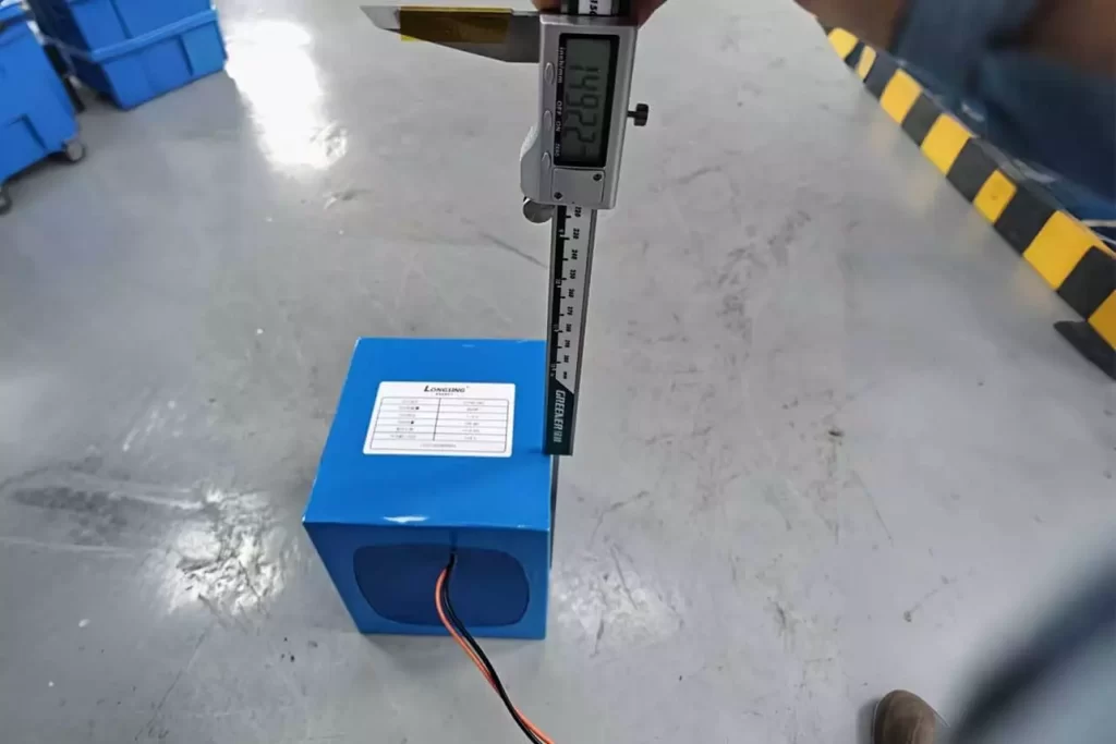
Installation followed a fixed sequence: verify the hull compartment is dry and de-energized, mount the pack, connect the negative lead first through the waterproof connector interface, confirm polarity and voltage before final seating, torque the bulkhead gland, then run a 24-hour load test before the buoy left the dock.
As a data buoy power system manufacturer, our chief engineer Jack Song signed off once the load test confirmed steady voltage under a simulated satellite uplink spike. Buyers sourcing a similar pack should request UN38.3 and IEC 62133 reports, confirm connector compatibility before committing to a cell format, and budget 6–8 weeks of lead time for a custom configuration.
Step-by-Step Battery Replacement & Maintenance Protocol
A well-run buoy monitoring system treats replacement as routine, not emergency work. Replacing a data buoy battery follows a fixed sequence: confirm the buoy is powered down at the load bus, record baseline voltage and capacity, disconnect the old pack at the connector interface, inspect the compartment for corrosion or water ingress[6], install the replacement, reconnect in the correct polarity, and run a load test before closing the hull.
Skipping the load test is the most common cause of a failed redeployment.
Field Maintenance Checklist
A maintenance protocol built around fixed intervals catches degradation in a marine data buoy system battery before it causes a mission failure. Visual inspection of the connector interface, gasket, and pressure-relief valve should happen at every service visit, regardless of battery age.
Tips
Most offshore battery failures originate from moisture ingress, connector corrosion or improper charging rather than cell degradation. Waterproof enclosure design is equally important, which should follow DNV Offshore Standards and the ABS Rules for Building and Classing Marine Vessels
Capacity testing — a controlled discharge against the pack’s rated Ah — should run annually for LiFePO4 packs and every six months for SLA. Internal-resistance testing flags cell imbalance before voltage sag becomes visible in the field, and many modern data buoy controllers log this automatically at every duty cycle.
Bouys in high-fouling or high-corrosion water, common on inshore weather buoy and wave buoy platforms, need a shorter inspection interval, and these bouys typically return to service within 48 hours of a completed swap.
- De-energize the load bus and confirm zero voltage at the battery terminals before opening the hull.
- Record baseline voltage, internal resistance, and any BMS fault codes from the outgoing pack.
- Disconnect the connector interface, positive lead first, negative lead last, to avoid an arc across a live load.
- Inspect the compartment gasket, desiccant, and pressure-relief point for wear or moisture.
- Seat the new pack, reconnect negative first then positive, and confirm polarity with a multimeter before powering the bus.
- Run a 24-hour load test and log the result before returning the buoy to service.
| Task | Interval | Pass Criteria |
|---|---|---|
| Visual inspection of connector interface and seals | Every service visit | No corrosion, cracking, or moisture |
| Capacity test (controlled discharge) | Annually (LiFePO4) / 6 months (SLA) | ≥80% of rated Ah |
| Internal resistance check | Every 6–12 months | Within 20% of baseline |
| BMS fault log review | Every service visit | No unresolved fault codes |
| Full pack replacement | End of rated cycle life or failed capacity test | N/A |
The same protocol applies across platform types — an offshore buoy battery replacement, an offshore monitoring battery upgrade, a battery for ocean sensor arrays, or a battery for marine telemetry radios all follow the same disconnect-inspect-test-reconnect sequence. A marine data buoy system battery moored in coastal shallows and one anchored in open water are, at this point in the workflow, functionally the same job.
Facing Rapid Battery Capacity Fade at Sea?
Upgrade to plug-and-play, IP68-sealed LiFePO4 packs designed for 10+ year buoy deployments.
Conclusion
Reliable buoy power comes down to matching chemistry and capacity to mission duration, sensor load, and solar resource, then following a tested installation and maintenance protocol.
A marine data buoy system battery sized against worst-case load rather than average load, built with a sealed connector interface, and paired with a documented replacement schedule keeps a data buoy transmitting through the darkest month of the year.
Buyers evaluating a data buoy battery pack should request cycle-life data, certification reports, and a defined lead time before specifying a final configuration.
Frequently Asked Questions
Click to explore more information about Marine Data Buoy System Battery
Q: What is the buoy system?
A: A buoy system is a network of anchored floating devices deployed in bodies of water, utilized for navigation, data collection, and environmental monitoring. Long Sing Energy designs the autonomous power solutions that keep these remote marine systems operational in harsh environments.
Q: What is a data buoy?
A: A data buoy is a specialized floating instrument platform equipped with various sensors to collect and transmit meteorological and oceanographic data, such as wave height, wind speed, barometric pressure, and water temperature.
Q: What is the Engineering behind Ocean Buoys?
A: Ocean buoys are engineered to withstand extreme marine conditions. Their design integrates stable hydrodynamic hulls, advanced telemetry systems for real-time satellite data transmission, marine-grade environmental sensors, and highly reliable power systems—like Long Sing Energy’s specialized battery packs—to ensure continuous autonomous operation.
Q: What is buoy used for?
A: Buoys are used for a wide variety of purposes, including marking safe navigational channels, warning mariners of underwater hazards, providing mooring points for vessels, and gathering vital weather and oceanographic data to support maritime safety and climate research.
Q: What are data marker buoys used for?
A: Data marker buoys serve a dual purpose: they act as visual navigational markers for specific maritime boundaries or hazards, while simultaneously collecting and transmitting localized environmental or meteorological data for scientific and commercial monitoring.
Q: What is the biggest buoy in the world?
A: The Lanby (Large Automatic Navigation Buoy) is traditionally considered one of the largest buoy types, historically weighing over 40 tons and measuring 12 meters (40 feet) across. Modern giant data buoys, like the deep-ocean moored buoys utilized by organizations like NOAA, also frequently reach 10 to 12 meters in hull diameter to support massive sensor payloads.
Q: How do buoy lights work and who replaces the batteries?
A: Buoy lights operate using high-efficiency LED technology powered by marine battery packs, which are frequently supplemented by solar panels for recharging. Routine maintenance and battery replacements are performed by national maritime authorities (such as the Coast Guard) or specialized marine contractors, though advanced, long-lasting battery solutions from companies like Long Sing Energy are designed to significantly extend these maintenance intervals.
Reference:
[1]Understand why telemetry is essential for remote monitoring systems.↪
[2]Compare PWM and MPPT charge control technologies. ↪
[3]Evaluate how deployment latitude affects solar energy availability.↪
[4]See why reserve days are critical for reliable marine power.↪
[5]Learn how biofouling reduces solar panel efficiency offshore.↪
[6]Learn how to prevent water ingress in marine battery compartments.↪