

Electric roller-skate developers must fit substantial energy and current capability into a small enclosure exposed to vibration, water and repeated acceleration. A weak electrical or mechanical match can reduce performance and increase safety risk. A structured micromobility battery pack design process connects vehicle requirements, protection functions, packaging and validation.
A suitable micromobility battery pack balances nominal and charging voltage, usable energy, continuous and peak current, installation dimensions, environmental protection, BMS functions, charger compatibility and applicable safety requirements. Designers should verify the lithium-ion battery pack as part of the complete vehicle because motor control, connectors, enclosure construction, software and operating conditions influence both performance and safety.
The following sections translate these requirements into practical decisions for OEM engineering and purchasing teams.
Table of Contents
- What Electrical Specifications Define a Micromobility Battery Pack?
- Which Safety Features Matter in Micromobility Battery Design?
- What Can a 43.2V 10Ah Electric Roller Skate Battery Case Study Show?
- When Should OEMs Choose a Custom Micromobility Battery Pack?
1.What Electrical Specifications Define a Micromobility Battery Pack?
The core specifications are nominal voltage, maximum charging voltage, ampere-hours, watt-hours and allowable charge and discharge current. Together they determine electrical compatibility, stored energy and power-delivery capability. A micromobility battery pack must match the motor controller and charger while remaining within the limits of its cells, BMS, conductors, connectors and thermal design.
Nominal voltage describes the pack’s normal operating level, while maximum charging voltage sets the upper limit for the charger and BMS. Series-connected cells increase voltage; parallel strings increase capacity and current capability. Ampere-hours measure charge capacity, whereas watt-hours estimate stored energy: nominal voltage multiplied by nominal ampere-hours. Watt-hours are therefore more useful than ampere-hours alone when comparing packs at different voltages.
Standard current identifies a representative operating or test condition. Maximum continuous current is sustainable only under defined thermal conditions. Because acceleration demand may be much higher than cruising demand, OEMs should provide current profiles rather than only motor wattage.
What Does 12S2P Mean?
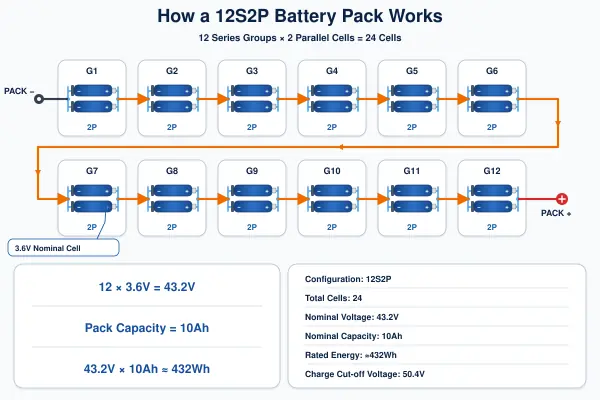
In a 12S2P battery pack, 12 cell groups are connected in series and each group contains two cells in parallel. For cells with a 3.6V nominal voltage, 12 series groups produce 43.2V nominal. The two parallel cells combine their capacity and share current. Cell ratings do not transfer directly to pack ratings because interconnects, BMS limits, enclosure temperature and matching quality also matter.
| Micromobility Battery Pack Parameter | What It Describes | Effect on Equipment |
|---|---|---|
| Nominal voltage | Typical pack operating voltage | Must match the controller and motor voltage window |
| Charging voltage | Permitted full-charge limit | Defines charger output and overvoltage threshold |
| Capacity (Ah) | Stored electric charge | Affects runtime within the same voltage platform |
| Energy (Wh) | Nominal voltage × capacity | Supports energy comparison across pack voltages |
| Continuous current | Sustainable current under defined conditions | Must cover sustained load without excessive heat |
| Peak current | Short-duration load capability | Supports acceleration but requires time and thermal limits |
Battery energy cannot determine exact range. Rider weight, terrain, speed, acceleration, temperature, rolling losses, controller behavior and drivetrain efficiency all change consumption. Estimates can guide selection, but an electric roller skate battery requires instrumented vehicle testing before an OEM publishes travel distance.
2.Which Safety Features Matter in Micromobility Battery Design?
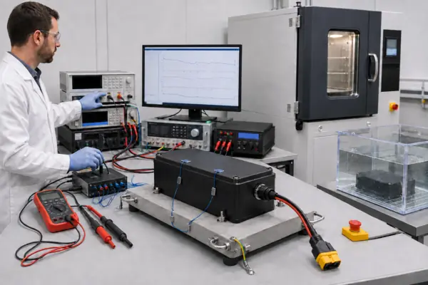
Battery safety depends on coordinated electrical, thermal and mechanical controls. The BMS should address cell overvoltage and undervoltage, excessive current, short circuit, abnormal charge and discharge temperatures and cell imbalance. The enclosure, connectors, charger and complete vehicle must then be validated together because a protected lithium-ion battery pack can still be exposed to hazards outside the BMS.
BMS, Connections and Environmental Protection
A BMS for micromobility monitors group voltage, pack current and temperature, then interrupts operation when calibrated limits are exceeded. Balancing can reduce voltage divergence but cannot repair damaged or poorly matched cells. Protection thresholds and delays must accommodate controller inrush and acceleration without unsafe limit increases.
The charger must match chemistry, series count, maximum voltage and current limits. Polarity, conductor size, contact resistance, retention and mating durability also require review. An anti-spark battery connector can limit arcing from controller capacitors, but does not replace overcurrent protection.
Micromobility battery pack protection from water and dust requires more than a gasket: glands, seams, fasteners and connectors are potential ingress paths. An IP67 battery pack target requires enclosure testing and post-test inspection[4]. Vibration or impact can damage connections and insulation, while trapped heat can accelerate aging. Sealing and thermal management must be developed together.
| Risk | Possible Cause | Engineering Control | Recommended Validation |
|---|---|---|---|
| Cell overcharge | Wrong charger or sensing fault | Cell-level overvoltage cutoff and charger matching | Protection-threshold and charger fault tests |
| Excessive current | Acceleration load, stall or short circuit | Rated cells, conductors, BMS and fuse strategy | Load profile, overcurrent and short-circuit tests |
| Water ingress | Seal, gland or connector leakage | Sealed enclosure and controlled assembly | Ingress test followed by insulation inspection |
| Connector heating | High resistance or poor retention | Rated locking connector and process control | Temperature-rise and mating-cycle tests |
| Thermal runaway | Cell defect, abuse or propagation | Cell qualification, spacing, barriers and system protection | Applicable cell, pack and system-level safety evaluation |
For North American programs, UL 2271 addresses batteries for light electric vehicle applications[1], while UL 2272 addresses electrical systems for personal e-mobility devices[2]. These are distinct scopes: a light electric vehicle battery evaluation is not the same as complete-device evaluation. UN 38.3 concerns lithium-cell and battery transport testing, not proof of vehicle-level safety[3].
In the United States, these UL standards have served as voluntary safety standards at the federal level. The CPSC published a notice of proposed rulemaking on June 24, 2026[5], proposing mandatory requirements based on applicable standards with modifications. As of August 2026, that proposal is not a final federal rule. OEMs should confirm the current status, product scope and local requirements with qualified compliance professionals.
3.What Can a 43.2V 10Ah Electric Roller Skate Battery Case Study Show?
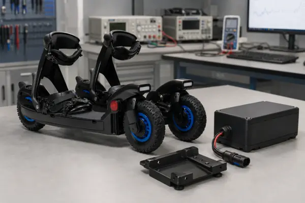
This anonymized personal e-mobility battery project illustrates how one specification becomes a system design. The rechargeable lithium-ion battery pack is rated at 43.2V, 10Ah and approximately 432Wh in a 12S2P configuration. Its current, temperature, connector and ingress requirements still need confirmation in the intended platform.
Supplied Project Specification
The 43.2V lithium-ion battery pack uses a 50.4V charge cutoff and a 30V discharge cutoff. Standard charging and discharging current is 2A, or 0.2C. Maximum continuous charging current is 10A, and maximum continuous discharge current is 30A. Charging is specified from 0°C to 45°C and discharging from −20°C to 60°C. Protection includes short-circuit and high- and low-temperature protection.
The project specification lists IP67 protection and anti-spark protection during connection and disconnection. These are design requirements, not certification claims. The supplied 260Wh/kg value applies to the individual cells, not the complete pack. No cycle-life figure is published here because the available descriptions of test conditions are inconsistent.
| Case-Study Specification | Engineering Purpose | Vehicle-Level Verification |
|---|---|---|
| 43.2V, 10Ah, approximately 432Wh rated energy | Defines voltage platform and nominal energy | Controller window, usable energy and range duty cycle |
| 12S2P configuration | Combines series voltage with parallel capacity | Cell-group matching and load sharing |
| 2A standard; 30A maximum continuous discharge | Defines reference and sustained-current conditions | Acceleration profile, temperature rise and BMS response |
| 10A maximum continuous charge; 50.4V cutoff | Sets upper charger boundaries | Charger communication, connector and thermal limits |
| 0°C to 45°C charge; −20°C to 60°C discharge | Defines specified operating windows | Sensor placement and protection accuracy |
| IP67 target and anti-spark connection | Addresses ingress and connection arcing | Sealing, mating cycles and post-test inspection |
This 432Wh battery pack may support motorized roller skates, but rated energy does not establish actual range. The electric roller skate battery must be tested with the selected motors, dual-side load distribution, controller settings, rider mass and representative surfaces.
Illustrative Failure Analysis: United States Personal E-Mobility Scenario
This is an illustrative engineering scenario, not a confirmed customer incident. Suppose rechargeable electric roller skates in the United States show intermittent shutdown, connector discoloration or increasing series-group imbalance. Possible contributors include water ingress, connector arcing, an incompatible charger or excessive acceleration current.
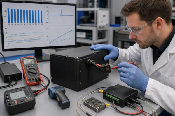
The investigation should preserve returned units and charger identity; inspect seals, contacts, welds, insulation, cells and BMS; and review cell-voltage, temperature, charging and discharging data. Root-cause work must distinguish initiation from secondary damage. Corrections may include improved sealing, higher-retention contacts, pre-charge, revised BMS calibration, tighter cell matching, charger keying or current control. Verification may repeat ingress, vibration, temperature-rise, connector-cycle, charge-abuse and acceleration-load tests.
Recommended Production and Validation Workflow
A practical micromobility battery pack workflow is:
- Verify the cell model, specification and approved supplier.
- Sort cells by open-circuit voltage and internal resistance.
- Assemble the 12S2P cell groups with controlled orientation and spacing.
- Inspect welding quality and electrical connections.
- Add insulation and structural protection against movement and abrasion.
- Install the BMS and specified temperature sensing.
- Verify wiring, polarity, connector ratings and anti-spark function.
- Assemble and seal the enclosure under controlled conditions.
- Perform charge and discharge testing against approved limits.
- Verify temperature sensing and protection functions.
- Conduct water-ingress and mechanical validation when required.
- Complete final quality inspection, identification and traceability records.
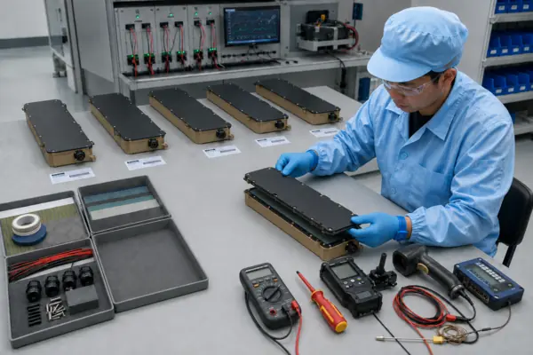
This is a recommended process, not a statement that every step was completed for the anonymized project. Process limits, sampling plans and test evidence should be agreed before pilot production.
4.When Should OEMs Choose a Custom Micromobility Battery Pack?
A standard product is appropriate when voltage, dimensions, current, connectors and operating conditions match the equipment. A custom micromobility battery is appropriate when these interfaces require application-specific electrical, mechanical, environmental or software work.
Standard Fit Versus Application-Specific Engineering
Restricted space may require a custom lithium-ion battery pack with a shaped enclosure, mounting points and controlled cable routing. Motor voltage, peak and continuous current, waterproofing, special connectors, communication protocols, BMS settings or charging behavior can also drive customization. For a micromobility battery pack, controller and charger information is required early to prevent integration errors.
| OEM Purchasing Factor | Standard Battery Pack | Custom Battery Pack |
|---|---|---|
| Electrical fit | Existing voltage and current ratings must match | Ratings and BMS settings developed for the load profile |
| Mechanical fit | Fixed dimensions, enclosure and mounting | Application-specific space, sealing and retention design |
| Interfaces | Existing connector and charging arrangement | Selected connectors, wiring and communication protocols |
| Development effort | Lower when all interfaces already align | Requires requirements control, samples and validation |
| Certification planning | Existing evidence must match the final use and scope | Design and test plan aligned with target markets |
| Production release | Qualification focuses on vehicle integration | Prototype, sample testing and pilot production precede scale-up |
The OEM should define target markets and certification goals before design freeze. European programs may also need a compliance plan for Regulation (EU) 2023/1542[6] and other product-specific legislation. An OEM battery pack manufacturer can support design and evidence preparation, but the final device manufacturer remains responsible for confirming which requirements apply to the complete product.
A rechargeable battery pack should move from requirements to samples, vehicle testing and pilot production with controlled revisions. For an electric roller skate battery, this sequence is especially important because compact packaging, two-foot load dynamics and exposed operating conditions interact in ways a standalone pack test may not reproduce.
Conclusion
A reliable micromobility battery pack starts with compatible voltage, energy and current, then adds coordinated BMS protection, connectors, sealing, mechanical design and system validation. Standard packs work when every interface already matches; otherwise, an application-specific design may be justified. LONGSINGX can discuss voltage, capacity, current, enclosure, connector, BMS and testing requirements for OEM projects before sample development and vehicle-level verification.
Frequently Asked Questions
Click to explore more information about Micromobility Battery Packs
Q: What is a micromobility battery pack?
A: A micromobility battery pack is a rechargeable battery system designed for compact personal transportation devices such as electric roller skates, e-scooters, e-skateboards and similar equipment. It typically combines lithium-ion cells, a BMS, wiring, connectors and a protective enclosure.
Q: What does 12S2P mean in a lithium-ion battery pack?
A: A 12S2P configuration contains 12 cell groups connected in series, with two cells connected in parallel in each group. The series connection determines pack voltage, while the parallel connection increases capacity and current capability.
Q: How much energy does a 43.2V 10Ah battery pack provide?
A: A 43.2V 10Ah battery pack has approximately 432Wh of rated energy, calculated by multiplying nominal voltage by nominal capacity. However, this figure cannot determine the exact travel range of electric roller skates without vehicle-level testing.
Q: What BMS protection is required for electric roller skates?
A: The BMS should provide cell overvoltage and undervoltage protection, overcurrent and short-circuit protection, charging and discharging temperature protection and cell balancing. Its current limits and response times should also match the motor controller and acceleration load.
Q: Does an electric roller skate battery need IP67 protection?
A: IP67 protection may be appropriate when the battery is exposed to water, dust and outdoor operating conditions. The complete enclosure, seams, cable glands and connectors should be tested to confirm the required ingress-protection performance. IP67 should not be described as certified without an official test report.
Q: Why is an anti-spark battery connector important?
A: An anti-spark connector helps reduce electrical arcing when the battery is connected to a motor controller with input capacitors. It can improve connector durability and connection safety, but it does not replace correct polarity, overcurrent protection or properly rated wiring.
Q: Should an OEM choose a standard or custom micromobility battery pack?
A: A standard pack may be suitable when its voltage, dimensions, current ratings, connectors and operating conditions already match the equipment. A custom battery pack may be necessary when the project requires restricted dimensions, special connectors, waterproof construction, specific BMS settings or application-specific charging and communication functions.
Q: How should an electric roller skate battery be tested?
A: Recommended validation may include charge and discharge testing, temperature-rise measurement, BMS protection verification, connector testing, vibration and impact testing and water-ingress testing. Final performance and safety should also be evaluated with the actual motors, controller, charger and vehicle operating conditions.
Reference:
[1] Review UL 2271 for batteries used in light electric vehicle applications.↪
[2] Learn how UL 2272 evaluates electrical systems for personal e-mobility devices.↪
[3] Review UN 38.3 transport testing requirements for lithium cells and batteries.↪
[4] Understand IEC 60529 enclosure protection classifications for water and dust ingress.↪
[5] Read the CPSC’s June 2026 proposed safety rule for micromobility lithium-ion batteries.↪
[6] Review Regulation (EU) 2023/1542 concerning batteries placed on the European market.↪