
The first question in a rack-level battery backup project is usually not battery capacity.
It is the power path.
A battery may contain enough energy to support a server rack for the required time and still be unsuitable if the cells, interconnects, converter or BMS cannot deliver the required power without excessive voltage drop or temperature rise.
That distinction is becoming more important as AI racks move toward much higher power density.
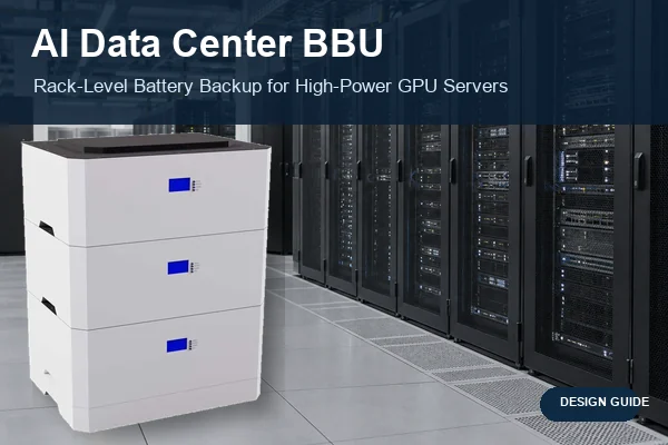
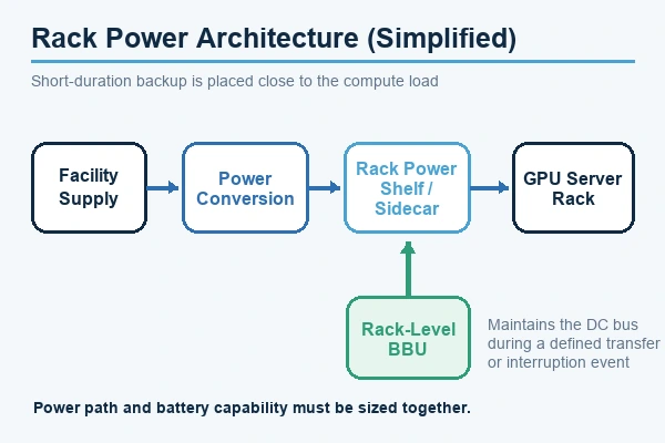
An AI data center BBU places short-duration battery backup close to the computing load. Depending on the architecture, the BBU may sit inside the rack, in a dedicated battery shelf or in an adjacent power sidecar. Its job is typically to maintain the DC bus through an upstream interruption or transfer event rather than provide long-duration facility backup.
That puts the design focus on several closely connected parameters: rack voltage, discharge power, ride-through time, current, thermal limits, redundancy and serviceability.
Table of Contents
1. Why Higher-Power AI Racks Change BBU Design
The Constraint Is No Longer Just Runtime
A conventional backup calculation often starts with load and runtime.
Rack-level backup adds another constraint: the battery has to deliver high power inside a relatively small mechanical envelope.
More cells can increase stored energy, but they also occupy space, add interconnections and change the cooling requirement. At the same time, higher rack power increases the current that has to move through cells, busbars, connectors and protection devices.
That is why BBU sizing cannot start from Ah or kWh alone.
Open Compute Project documentation treats backup storage, DC distribution and high-density rack power as parts of the same system-level problem. Its Rack & Power work includes BBU integration in architectures intended to support increasingly high rack power. [1]
48V Is Established, but Higher Voltage Is Moving Closer
Rack-level battery backup already exists in lower-voltage DC systems.
The Open Rack V3 BBU specification, for example, defines a 48V-class rack BBU architecture. The BBU module combines the battery, BMS and charge/discharge control functions and is designed to support the rack during loss of upstream AC power. [2]
At higher power, current becomes harder to manage.
P = V × I
Imagine a DC bus supplying 50 kW. Ignoring conversion losses for a moment:
- At 48V, 50 kW corresponds to about 1,042 A.
- At 800V, the same power corresponds to about 62.5 A.
This is a bus-level illustration rather than a battery-pack specification, but it explains the electrical motivation behind higher-voltage distribution.
Lower current can reduce conductor and busbar burden. It can also reduce some resistive losses.
Higher voltage introduces a different set of requirements: insulation, connectors, contactors, protection, creepage and clearance, fault isolation and service procedures all have to be designed for the higher-voltage environment.
Industry work around 800 VDC therefore should not be read as “48V is obsolete.”
Google, Microsoft and NVIDIA are working through OCP on common 800 VDC requirements for next-generation AI infrastructure. OCP describes 800 VDC as an additional deployment architecture that can coexist with today’s AC infrastructure, including side-power-rack and longer-term direct-MVAC-to-800-VDC approaches. [3]
800 VDC is becoming an important design direction, but it is not yet a universal data-center architecture.
2. What a Rack-Level BBU Actually Has to Deliver
Start With the Ride-Through Requirement
A BBU normally exists to bridge a defined power event.
The required duration could be related to source transfer, upstream recovery, generator transition or another system-level event. There is no universal BBU runtime that applies to every data center.
One useful reference is OCP’s Open Rack V3 specification. Its defined architecture uses 3 kW BBU modules with at least four minutes of discharge capability under specified conditions, arranged in a 5+1 shelf configuration. [2]
Those values describe that particular OCP architecture. They should not be copied directly into another project.
For an OEM or power-system designer, the more useful sequence is:
required rack power → required ride-through time → DC-bus window → redundancy → battery configuration
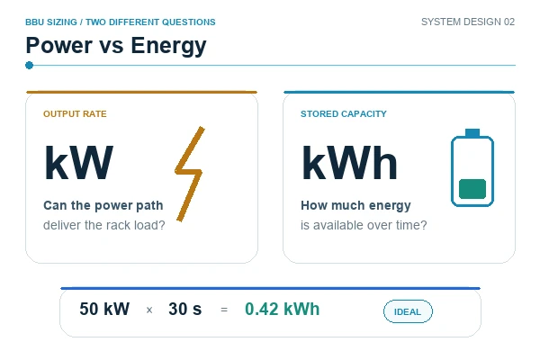
Power and Energy Are Different Sizing Problems
The battery still needs sufficient energy, but BBU applications often make the power requirement especially visible.
For example, supporting 50 kW for 30 seconds requires an ideal energy quantity of only about 0.42 kWh:
50 kW × 30 / 3600 ≈ 0.42 kWh
The energy number is small. Delivering 50 kW safely is not necessarily small.
The cell configuration, internal resistance, DC-bus voltage, conversion stage and interconnect design all determine whether that power can actually reach the load. This is where a battery selected only by nominal capacity can fail.
Current Capability, Voltage Sag and Interconnects
At high discharge power, pack performance is not determined by the cells alone.
Resistance exists through the entire current path:
cell → weld / connection → busbar → fuse → contactor → connector → converter
Each part contributes voltage drop and heat.
Because resistive heating follows I²R, increasing current can create a much larger thermal burden even when the backup event is short. That makes voltage sag an important specification.
The battery has to remain above the minimum usable voltage of the DC system while delivering the required power at the specified SOC, temperature and aging condition. A design that works comfortably on a new battery at room temperature may have much less margin after calendar aging or at the lower end of its SOC window.
Cell Selection Should Follow the Electrical Architecture
There is no single “best BBU cell.”
Cylindrical lithium-ion cells can be attractive where modular construction, compact packaging and high discharge capability fit the design. LiFePO4 may be considered where its chemistry and system-level characteristics better match the stationary application.
The important point is that chemistry and cell format should come after the electrical requirements are known.
Voltage → Power → Duration → Current → Mechanical Space → Thermal Boundary → Life Requirement → Cell Architecture
For cylindrical-cell designs, cell consistency also matters. Differences in capacity, open-circuit voltage and resistance can affect how evenly parallel cells share current and which series group reaches a protection limit first. For a deeper discussion, see LONGSING’s Battery Cell Matching guide.
The BMS Has to Know Whether the BBU Is Still Ready
A BBU may spend far more time on standby than in deep discharge. That changes what battery health means.
A pack can complete relatively few discharge cycles and still lose power capability through calendar aging, elevated temperature or increasing internal resistance.
The BMS therefore has to support the operating role of the BBU rather than simply report voltage and SOC. Depending on the architecture, useful functions can include cell-voltage and temperature monitoring, current measurement, balancing, fault logging, protection control, SOC, SOH and communication with the rack power system.
For a backup battery, the useful SOH question is not only how much capacity remains. It is also: Can the battery still deliver the required rack power for the specified ride-through period?
3. Rack-Level BBU vs Centralized UPS
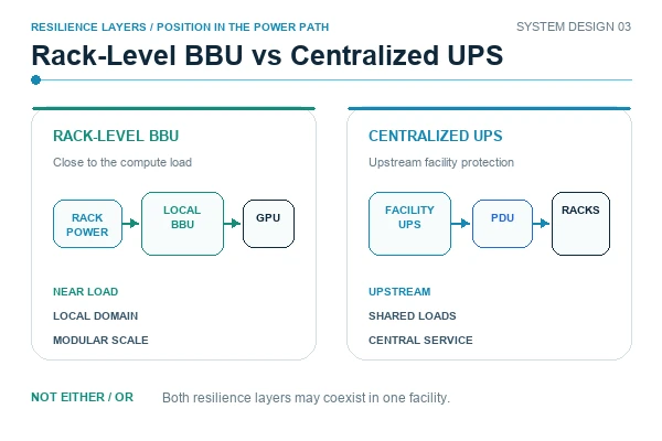
Rack-level BBUs and centralized UPS batteries belong to the same overall resilience problem, but they protect the load at different points in the power system.
| Engineering Point | Rack-Level BBU | Centralized UPS |
|---|---|---|
| Position | In the rack, battery shelf or adjacent power rack | Upstream facility power system |
| Protected load | Individual rack or rack group | Larger group of critical loads |
| Backup architecture | Distributed | Centralized |
| Primary design focus | Rack power, DC bus and short ride-through | Facility continuity and defined UPS runtime |
| Current path | Close to the compute load | Through upstream UPS and distribution |
| Scaling | Add rack or module capacity | Expand centralized UPS or battery blocks |
| Failure domain | More localized | Potentially broader |
| Service approach | Module-level replacement may be possible | Depends on UPS topology and facility redundancy |
| Voltage | Architecture-specific; 48V established, higher-voltage DC emerging | Depends on UPS and battery design |
Neither approach is inherently better. They solve different parts of the power-continuity problem and may exist in the same facility.
A simplified hierarchy could be:
Utility / Facility Supply → Facility UPS or Other Resilience Layer → Power Distribution → Rack Power System → Rack-Level BBU → AI Compute Load
Real facilities may arrange these layers differently. LONGSING’s existing article on data center UPS battery design covers the facility-level battery side in more detail. Facility UPS runtime and rack-level ride-through are not the same engineering problem.
4. How to Specify an AI Data Center BBU Battery
For a battery supplier, “we need a BBU for an AI rack” is not yet a usable specification.
The first RFQ should describe the electrical interface and operating role.
| RFQ Item | Information to Provide |
|---|---|
| DC architecture | Rack-level, sidecar or other topology |
| Nominal voltage | Required battery / DC-bus voltage |
| Voltage window | Minimum and maximum operating voltage |
| Continuous power | Required sustained discharge power |
| Peak power | Magnitude and duration |
| Ride-through time | Required backup duration |
| Maximum current | System or battery current limit |
| Allowed voltage sag | Minimum usable voltage under load |
| Redundancy | N, N+1 or another project requirement |
| Mechanical space | Maximum L × W × H or rack-unit envelope |
| Weight | Module or shelf limit |
| Cooling | Airflow, forced air, liquid interface or other boundary |
| Environment | Operating and storage temperature |
| Communication | CAN, RS485, SMBus, Ethernet or project-defined interface |
| SOC / SOH | Required monitoring and reporting |
| Service method | Fixed module, replaceable module or hot-swap requirement |
| Compliance | Intended market and certification target |
| Service life | Calendar-life target |
| Duty profile | Expected tests, backup events and cycling frequency |
Mechanical Design Can Limit the Battery Before Capacity Does
A rack envelope includes more than cell volume. Space is also needed for busbars, insulation, connectors, handles, cooling paths, protection devices and module removal.
Service access deserves particular attention. A battery module that fits inside the rack during assembly may still be impractical if another rack component has to be removed every time the battery is serviced.
For modular BBU systems, module weight, insertion force, connector alignment and replacement procedure can matter almost as much as total pack energy.
Thermal Design Includes the Entire Current Path
High-rate discharge produces heat in the cells, but local hotspots can also occur at interconnects, busbars, terminals and connectors.
Thermal review should cover cells + module structure + electrical connections + airflow or cooling interface, rather than treating the cell datasheet temperature limit as the complete thermal design.
The cooling boundary also needs to be clear between battery supplier and rack integrator. If rack airflow is assumed to remove battery heat, the airflow conditions and temperature limits need to be part of the interface specification.
Redundancy Has to Match the Failure Strategy
OCP’s Open Rack V3 design uses a 5+1 BBU shelf arrangement, but that is one implementation rather than a rule for every rack. [2]
Another project may use N modules, N+1, distributed sidecar modules or a different service strategy.
The correct arrangement depends on what should happen when one battery module is unavailable, one converter fails, a module is removed for maintenance, the remaining modules have aged, or the rack is operating close to maximum power.
Redundancy should therefore be specified as a system requirement rather than inferred from the number of battery modules.
Safety Requirements Depend on the System Boundary
Battery standards, complete-system standards and installation codes do not cover exactly the same thing.
IEC 62619:2022 covers safety requirements and tests for secondary lithium cells and batteries used in industrial applications, including stationary applications such as UPS and energy-storage systems. [4]
For North American stationary applications, UL 1973 applies to batteries used in stationary and related applications, while UL 9540 addresses complete energy-storage systems and equipment. [5]
UL 9540A is different again. It is a test method for evaluating thermal-runaway fire propagation in battery energy-storage systems; it should not be described as a general battery-pack certification. [6]
For stationary ESS installations, NFPA 855 provides installation-level requirements. The current edition is 2026. [7]
The applicable path for a rack BBU depends on how the product is classified, the complete system architecture, installation environment and target jurisdiction. A battery supplier should confirm the required compliance boundary with the OEM or system integrator before the design is frozen.
From RFQ to Battery Architecture
LONGSING develops rechargeable battery solutions around application-specific electrical and mechanical requirements, including cylindrical lithium-ion cells, LiFePO4 batteries, custom battery packs, high-voltage battery packs and BMS integration.
For a rack-level backup project, development should begin with the real system inputs: voltage window, power profile, ride-through requirement, thermal boundary, mechanical envelope, communication and compliance target.
Only after those parameters are clear does it make sense to decide the cell format, series/parallel configuration, BMS architecture and module construction.
This is especially important for emerging AI power architectures. A conventional battery pack should not be assumed to be suitable for a BBU simply because its nominal voltage or stored energy appears close to the requirement. LONGSING’s comparison of 18650, 21700 and prismatic cells provides more context on cell-format tradeoffs.

Review Your AI Data Center BBU Requirements
Send the DC-bus voltage window, continuous and peak rack power, required ride-through time, mechanical envelope, cooling boundary and communication requirements for an engineering feasibility review.
Conclusion
AI data center BBU design is not a capacity-first decision. It begins with the rack power architecture, voltage, ride-through duration and failure strategy. Battery cells, interconnects, the BMS, thermal design and service method must then be evaluated as one power path. For project-specific development, LONGSING can review the electrical, mechanical, communication and compliance inputs before proposing a battery architecture.
Frequently Asked Questions
Click to explore more information about AI data center BBUs
1. What is a BBU in an AI data center?
A Battery Backup Unit provides temporary battery power close to a server rack or rack DC bus when the normal upstream source is interrupted. It is normally designed around a defined ride-through requirement rather than long-duration energy storage.
2. How is a rack-level BBU different from a UPS?
The main difference is where the backup sits in the electrical architecture. A rack BBU protects a rack or local DC bus, while a centralized UPS usually protects a wider group of facility loads upstream. A data center can use both.
3. Why are rack-level BBUs becoming more relevant for AI servers?
Higher rack power increases the electrical and thermal burden on local power delivery. Placing short-duration backup closer to the compute load can support a defined local DC bus and limit the backup domain, but the correct architecture still depends on the facility and rack design.
4. Does every AI data center BBU require 800 VDC?
No. 48V-class rack BBU architectures are established, while 800 VDC is an emerging direction for higher-density infrastructure. The battery voltage must follow the actual system architecture; 800 VDC should not be treated as a universal requirement.
5. How much runtime should a rack-level BBU provide?
There is no universal runtime. It should be defined from the event the BBU must bridge, the required rack power, source-transfer or recovery time, DC-bus limits and redundancy. OCP values describe specific architectures, not a default for every project.
6. Which battery chemistry is best for an AI server BBU?
No single chemistry is best for every BBU. Cylindrical lithium-ion and LiFePO4 may both be considered depending on power, voltage, space, thermal conditions, service life and compliance. Cell format and chemistry should be selected after the electrical requirements are known.
7. What information should a BBU RFQ include?
The RFQ should define DC architecture, voltage window, continuous and peak power, ride-through time, current limit, allowable voltage sag, redundancy, mechanical envelope, cooling, communication, service method, environment and compliance target.
8. Can an existing lithium battery pack be used as a BBU?
Not automatically. A pack may have similar nominal voltage or energy and still fail the required power, voltage-sag, thermal, communication, redundancy or service criteria. Suitability must be verified against the complete rack power path and operating boundary.
References
[1] Open Compute Project. Rack & Power project and BBU architecture resources. ↪
[2] Open Compute Project. Open Rack V3 BBU Module Specification 1.4. ↪
[3] Open Compute Project. Industry transition toward standardized 800 VDC for next-generation AI infrastructure. ↪
[4] Industrial secondary lithium battery safety requirements. ↪
[5] Stationary battery and complete energy-storage-system safety boundaries. ↪
[6] Thermal-runaway fire-propagation testing for battery energy-storage systems. ↪
[7] Stationary energy-storage-system installation requirements. ↪