

During normal driving, an eCall module or telematics control unit is usually powered by the vehicle electrical system. The more difficult condition comes after that supply is lost.
A collision can disconnect the primary power path, damage wiring or leave the available voltage below the range the telematics electronics can use. Yet the system may still need to determine vehicle position, register on the mobile network, transmit emergency information and support a voice call.
That is where an eCall backup battery becomes part of the design.
The engineering problem is not simply how many mAh to install. The battery must store enough energy for the required emergency sequence while still maintaining sufficient voltage when the modem, processor and audio circuit place a heavier load on it.
A cell can meet the nominal capacity target and still fail the system if its loaded voltage falls below the usable input range of the DC/DC converter.
Featured Snippet: How Do You Select an eCall Backup Battery?
An eCall backup battery should be selected from the complete emergency load profile, required operating time, peak current, minimum usable voltage, charging architecture, temperature and expected battery aging. LiFePO4 can suit some low-voltage backup designs, but the final chemistry and capacity must be matched to the actual telematics system.
Table of Contents
- Why Does an eCall System Need Backup Power and What Must It Support?
- How Should an eCall Backup Battery Be Selected?
- How Do Power Path, Charging, Temperature and Aging Affect the Design?
- What Do EU eCall Requirements Mean for Battery Development?
1. Why Does an eCall System Need Backup Power and What Must It Support?
Under normal conditions, vehicle power supplies the telematics electronics and can also maintain a rechargeable backup cell through the charging circuit.
An accident can change that situation very quickly.
The main supply may be physically disconnected, wiring may be damaged, or the voltage may fall below the minimum input required by the telematics power stage. If emergency communication still has to continue, the system needs another usable energy source.
A simplified normal power path is:
Vehicle power → power management → eCall / TCU electronics
When primary power is lost:
Backup battery → DC/DC conversion → eCall / TCU system rail
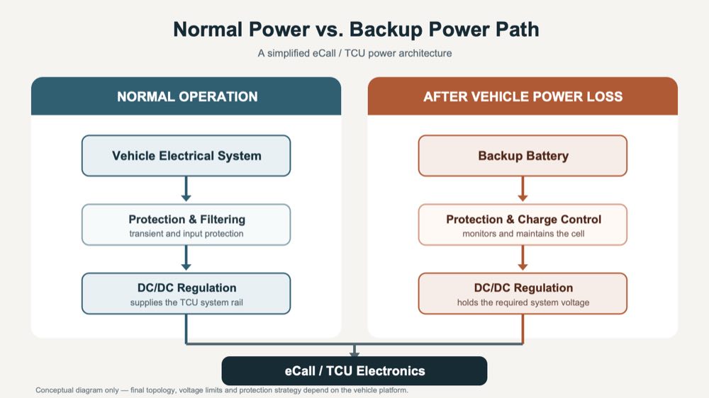
The backup battery is therefore not the same as the vehicle starter or auxiliary battery. It is a smaller secondary source designed specifically around the functions that have to remain active after loss of the normal vehicle supply.
What Happens When the Main Vehicle Supply Fails?
Battery capacity is only one part of the changeover.
The power electronics also have to recognize that the main supply is no longer usable and move the critical load onto backup power without an uncontrolled reset.
If the processor or modem restarts at the wrong point, the system may need to repeat network registration or other parts of the emergency sequence.
This is why the battery, converter and power-path control should be considered together rather than treating the backup cell as an isolated component.
What Does the Backup Battery Actually Power?
An eCall system does not draw one constant current.
Different functions become active at different stages:
| Operating State | Typical Active Functions |
|---|---|
| System monitoring | MCU and essential monitoring circuits |
| Emergency trigger | Processor and system control |
| Positioning | GNSS receiver and processing |
| Network registration | Cellular modem and RF section |
| Emergency data transmission | Modem and processor |
| Voice communication | Modem, MCU, microphone path, amplifier and speaker |
| Call-back standby | Network registration and essential system control |
Voice communication can be particularly relevant because the modem and audio path remain active at the same time.
This creates a different electrical profile from a simple IoT tracker that wakes briefly, sends a packet and returns to sleep.
For battery sizing, measurements from the complete telematics unit are therefore more useful than a single current value taken from the modem datasheet.
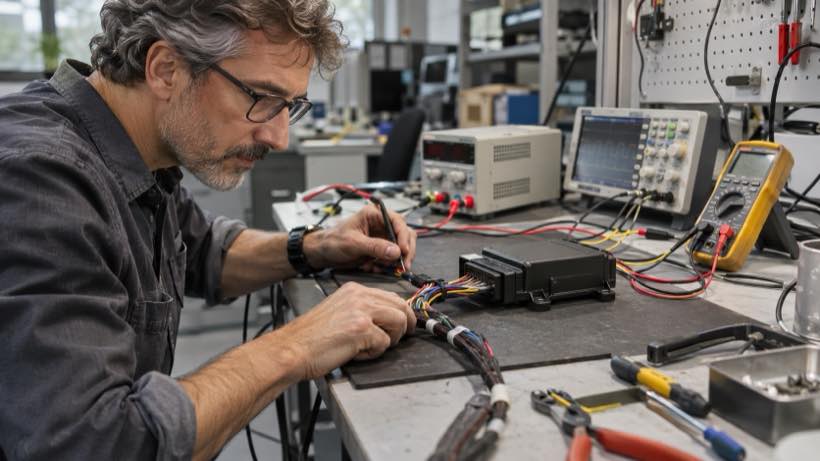
The eCall backup battery has to satisfy both the energy requirement of the complete emergency sequence and the power requirement of its highest-load stages.
2. How Should an eCall Backup Battery Be Selected?
Battery selection normally starts with energy, but it should not end there.
If the power used in each operating state is known, an early estimate can be made from:
Required Energy ≈ Σ (Power × Time)
The battery-side requirement must then account for power-conversion losses and the portion of the battery voltage range the system can actually use.
Energy and Peak Power Are Different Problems
Energy determines how long the system can continue operating.
Peak power determines whether the battery can support a particular load without excessive voltage drop.
Consider an aged battery during a voice call.
The cell may still contain enough stored energy to complete the required operating period. But if internal resistance has increased, the higher load from the modem and audio amplifier can pull the battery voltage down.
Cold temperature can make the same effect more pronounced.
If the voltage then falls below the converter’s usable input range, the eCall electronics can reset even though usable capacity remains in the cell.
A useful battery specification should therefore include more than Ah:
- operating voltage range;
- required energy;
- continuous load;
- peak load and duration;
- minimum acceptable loaded voltage;
- operating temperature; and
- expected battery condition near end of life.
Increasing capacity alone cannot correct every power-delivery problem.
Where LiFePO4 Fits in eCall Backup Power
LiFePO4 is one practical rechargeable chemistry for certain eCall and T-Box architectures.
Texas Instruments’ TIDA-050031 backup-power reference design uses a single LiFePO4 cell for an automotive emergency calling application. 【1】
In that architecture, vehicle power normally feeds the system and charges the backup battery. If the main supply browns out, the LiFePO4 cell supports the system through a boost converter.
That makes single-cell LiFePO4 a technically relevant design direction, but it should not be interpreted as a universal requirement.
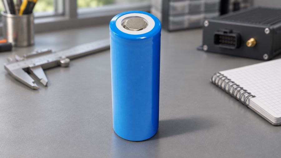
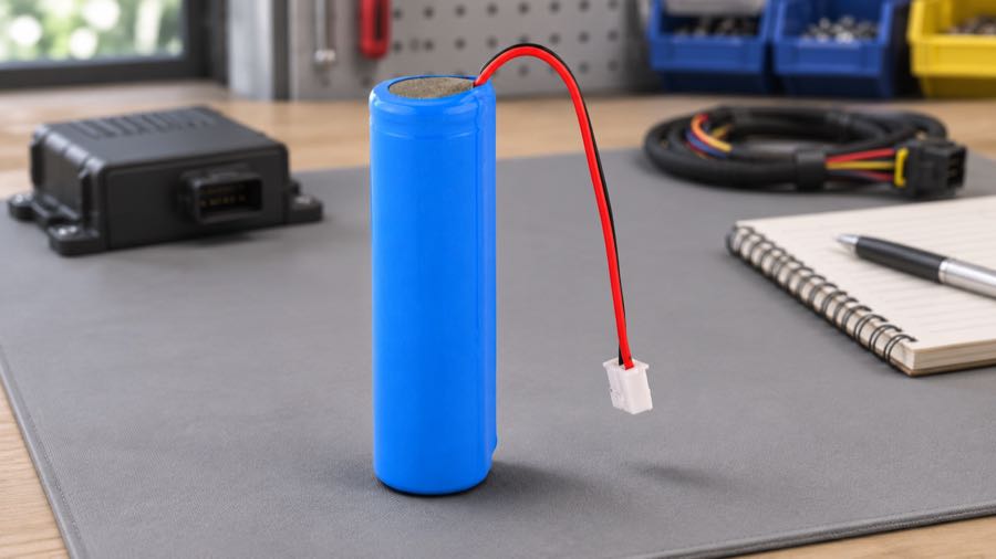
Conventional Li-ion and lithium-polymer cells may also suit applications where packaging volume, cell voltage or energy density leads to a different architecture.
| Design Factor | LiFePO4 | Conventional Li-ion |
|---|---|---|
| Nominal cell voltage | Lower | Higher |
| Energy density | Generally lower | Generally higher |
| Charging | Requires LiFePO4-specific profile | Requires chemistry-matched Li-ion profile |
| Packaging | May require more volume for equivalent energy | Can be useful where available space is limited |
| Application fit | Useful in selected low-voltage backup systems | Useful in other voltage and packaging architectures |
The choice should follow the system rather than a general preference for one chemistry.
Available space, voltage architecture, emergency load, charging strategy, temperature and required service life all matter.
Battery Capacity Should Follow the Real Load Sequence
A conceptual eCall event may look like:
Standby → emergency trigger → GNSS → network registration → data transmission → voice call → call-back standby → possible second voice call
The load is different in each stage.
A more reliable eCall backup battery sizing process is to measure the actual system through this sequence, calculate energy consumption, identify the highest current demand and then check the battery voltage under those conditions.
Final sizing should also consider converter efficiency and the minimum voltage at which the system can still operate.
3. How Do Power Path, Charging, Temperature and Aging Affect the Design?
A rechargeable backup battery spends most of its life connected to a system rather than actively powering an emergency call.
That creates a different set of design concerns from a battery that is discharged every day.
Power-Path Design Has to Prevent an Unexpected Reset
Under normal operation:
Vehicle supply → power converter → telematics electronics
while the rechargeable backup battery is maintained by the charger.
After primary-power loss:
Backup battery → DC/DC converter → system rail
Depending on the cell voltage and required system rail, this may involve boost, buck or buck-boost conversion.
The design may also use undervoltage detection, power-fail monitoring, ORing or ideal-diode functions to manage the transition between sources.
For an eCall backup battery, one of the most useful parameters is the minimum usable battery voltage.
A cell datasheet may define a wider discharge range than the telematics electronics can actually use. If the DC/DC stage reaches its lower input limit earlier, the remaining electrochemical capacity is no longer useful to the system.
Charging Must Match the Selected Chemistry
Rechargeable backup cells need an appropriate charging strategy.
LiFePO4 does not use the same charge-voltage profile as conventional Li-ion chemistry. Selecting a charger simply because it is described as suitable for “lithium batteries” is not enough.
The design should define:
- charge voltage and current;
- charge termination;
- charging temperature limits;
- long-term maintenance strategy; and
- protection against abnormal charging conditions.
A small one-cell backup battery also does not automatically require a complex smart BMS.
Depending on the architecture, protection and monitoring may be divided between the cell protection circuit, charger IC, power-management IC, temperature sensing and the host electronics.
Calendar Aging Can Matter More Than Cycle Count
An eCall backup battery may remain installed for a long period while rarely seeing a deep discharge.
It is still aging.
Long periods at relatively high state of charge and exposure to elevated vehicle temperatures can affect battery condition even when cycle count remains low.
For this kind of application, calendar aging deserves particular attention.
High temperature may accelerate long-term degradation. Low temperature creates a different problem by increasing cell resistance and reducing loaded-voltage margin.
A pack that performs comfortably at room temperature can behave differently after sitting in a cold vehicle and then immediately supporting network registration and voice communication.
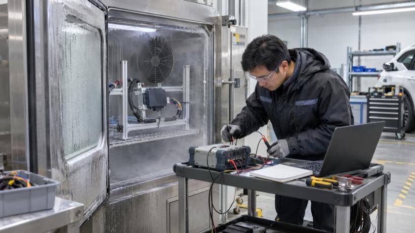
The useful engineering questions are therefore:
Can the battery deliver the required power at the lowest project temperature?
and
Will it still have sufficient energy and voltage margin near the end of the intended service period?
The answers should come from the selected cell and project validation rather than from a generic automotive temperature claim.
4. What Do EU eCall Requirements Mean for Battery Development?
EU eCall requirements provide an important system-level design input, particularly for projects targeting the European market.
Commission Delegated Regulation (EU) 2025/1871 updated the existing 112-based eCall framework and introduced a verification procedure for backup power where a backup supply is fitted. 【2】
The test sequence includes:
at least 5 minutes of voice communication
followed by
60 minutes in call-back mode while registered on the network
followed by
at least another 5 minutes of voice communication.
This does not translate directly into a battery specification such as “70 minutes of battery capacity.”
Voice operation and registered standby have different electrical loads. Converter losses, temperature, battery aging, speaker demand and modem behaviour can also change the energy required.
The regulation therefore defines what the system must be able to do. Battery capacity still has to be derived from the actual electrical design.
The Move Toward Packet-Switched eCall
The European eCall framework is also being updated for packet-switched telecommunications technology.
Commission Delegated Regulation (EU) 2024/1180 and related standards introduce requirements associated with newer eCall communication architecture, with further provisions applying from 1 January 2027. 【3】
This should not be simplified into a statement that every existing 2G eCall system stops working or becomes non-compliant on that date.
From a battery-engineering perspective, the more useful point is that a new modem or telematics platform may behave differently from the older system it replaces.
Network registration time, processor activity and voice communication load can change.
When the telematics hardware changes, the backup-battery load profile should be measured again.
Information an OEM Should Send to the Battery Supplier
A request such as “3.2 V 1500 mAh eCall battery” provides very little information about the real application.
For custom development, the following inputs are more useful:
| Project Input | Information to Provide |
|---|---|
| Electrical window | Required system voltage and minimum usable battery voltage |
| Load data | Average, continuous and peak load, including peak duration |
| Emergency sequence | Required operating states and duration |
| Charging | Charger voltage, current and maintenance strategy |
| Mechanical | Available L × W × H, connector, wire length and mounting |
| Environment | Operating, charging and storage temperature requirements |
| Battery life | Expected installation period and replacement strategy |
| Protection | Required electrical protection and temperature sensing |
| Qualification | OEM, Tier-1, regulatory and target-market requirements |
Measured system data is considerably more useful than selecting a cell from capacity alone.
Where LONGSING Fits
For an eCall module, T-Box, TCU or related telematics device, LONGSING can evaluate rechargeable battery designs from the electrical and mechanical requirements of the project.
Development inputs can include cell chemistry, voltage and capacity, protection circuit, connector, wiring, NTC requirements and pack dimensions.
The qualification path still has to be defined for the specific automotive project. Supplying a battery pack does not by itself make the completed telematics system compliant with an OEM or eCall regulatory requirement.
Review Your eCall / T-Box Battery Requirements
Prepare the system voltage range, emergency load profile, peak current, minimum usable voltage, available battery space, charging method, temperature requirements and expected installation period for an engineering feasibility review.
5. Conclusion
An eCall backup battery has a relatively specific purpose: keeping essential telematics functions available when the normal vehicle power path can no longer be relied upon.
The battery may spend years waiting for that event, which makes the design different from a frequently cycled consumer battery.
Enough energy has to remain available for the required operating sequence, but the cell must also maintain sufficient voltage during modem and audio loads. Charging, low-temperature performance, calendar aging and the DC/DC power path therefore belong in the same engineering discussion as nominal capacity.
LiFePO4 can be a practical option for selected low-voltage backup architectures. Conventional Li-ion and lithium-polymer cells can fit other designs.
The final choice should follow the actual TCU or eCall system: its load profile, voltage limits, available space, temperature environment and required service life.
For a custom battery evaluation, provide these operating conditions first. They allow the battery design to be developed around what the telematics hardware actually needs after vehicle power disappears.
Frequently Asked Questions About eCall Backup Batteries
Click to explore more information about eCall backup battery design.
Q: Why does an eCall system need a backup battery?
A: A backup battery can maintain essential emergency communication functions if the primary vehicle supply is disconnected, damaged or falls below the system’s usable voltage.
Q: What type of battery is used for eCall?
A: There is no universal battery chemistry. LiFePO4, conventional Li-ion, lithium-polymer and other rechargeable technologies may be considered depending on the voltage architecture, power demand, packaging, charging and temperature requirements.
Q: Can LiFePO4 be used as an eCall backup battery?
A: Yes. Single-cell LiFePO4 has been used in published automotive eCall backup-power reference architectures. Its suitability still depends on the actual system voltage, load profile, charging method, temperature and project validation requirements.
Q: How long does an eCall backup battery need to operate?
A: EU backup-power verification includes voice communication and registered call-back periods, but this is a system operating sequence rather than a direct battery-capacity specification. The required battery energy depends on the load during each state.
Q: How do I calculate eCall backup battery capacity?
A: Measure the complete system power during each required operating state, calculate the energy used over time and account for converter efficiency. Then verify peak current, loaded voltage, temperature and expected aging with the actual hardware.
Q: What is the difference between an eCall battery and a T-Box battery?
A: eCall specifically addresses emergency communication. A T-Box or TCU may also support vehicle connectivity, positioning, remote diagnostics, OTA services and other functions, so its backup-power requirement depends on which functions must remain available.
Q: Does every TCU need a backup battery?
A: No. Some telematics units rely only on vehicle power. A backup battery becomes relevant when the system specification requires defined functionality after the primary vehicle supply is lost.
Q: Why does low temperature matter for an eCall battery?
A: Low temperature can increase cell resistance and deepen voltage drop under load. The system may therefore reach its minimum usable voltage sooner during modem or audio operation even when stored energy remains.
References