
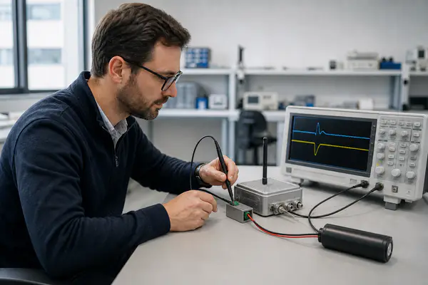
An IoT device may run normally for months, then reset whenever its radio transmits. Replacing the battery may only delay the problem. Identifying the source of the voltage drop—and validating the complete power path—prevents repeated field failures.
IoT battery voltage drop occurs when transmission current passing through battery, connector, wiring, PCB, and converter resistance pulls the load voltage below the device’s operating threshold. Low temperature, passivation, aging, repeated network attempts, or an unsuitable power architecture can increase the drop. A hybrid pulse capacitor may support short current bursts, but the solution must be sized and tested against the actual load profile.
Understanding when and where the voltage falls is the first step toward selecting a reliable IoT power solution.
Table of Contents
- Why Does an IoT Battery Voltage Drop During Wireless Transmission?
- How Can Engineers Diagnose an IoT Battery Voltage Drop Failure?
- When Can a Hybrid Pulse Capacitor Reduce IoT Battery Voltage Drop?
- How Should a Custom ER + HPC Battery Pack Be Designed and Validated?
Why Does an IoT Battery Voltage Drop During Wireless Transmission?
An IoT battery voltage drop usually occurs because wireless transmission demands substantially more current than sleep-mode operation. Current passing through the total source resistance produces voltage sag. If the load voltage falls below the minimum voltage of the modem, microcontroller, or converter, the device may reset even though the battery retains usable capacity.
Sleep Current and Transmission Pulses Are Different Design Conditions
An IoT device may spend most of its life asleep, but processor wake-up, network registration, sensing, positioning, and data transmission create a changing load profile. Power Saving Mode reduces standby consumption but does not eliminate demanding communication events. 【1】
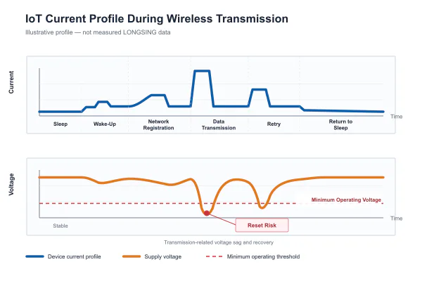
| Operating phase | Typical power behavior | Possible risk |
|---|---|---|
| Sleep | Low, relatively stable device-specific current | Leakage and self-discharge dominate |
| Wake-up | Short increase as circuits start | Initial voltage sag |
| Network registration | Variable radio activity | Longer active time under weak coverage |
| Transmission | Short, high current pulses | Reset or modem shutdown |
| Retry | Repeated or extended pulses | Insufficient recovery time |
| Return to sleep | Current falls and voltage recovers | Fault may disappear during inspection |
How Internal Resistance Converts Current into Voltage Sag
ΔV ≈ I × R
Here, I is instantaneous load current and R is the total resistance of the battery, terminals, welds, wiring, connectors, PCB, protection components, and converter input path.
For example, a 300 mA pulse through 2 Ω creates an estimated 0.6 V drop, pulling a nominal 3.6 V source toward 3.0 V before other transient effects.
An acceptable open-circuit voltage does not rule out IoT battery failure, because a multimeter may miss a brief loaded event. Li-SOCl₂ passivation limits self-discharge but can also cause initial voltage delay after storage. 【2】
Why Weak Signal Conditions Can Make the Problem Worse
Transmission demand depends on radio conditions, protocol, payload, firmware, antenna performance, and retransmissions. Weak coverage can extend radio-on time. LTE-M and NB-IoT also differ: Nordic Semiconductor reports that LTE-M may use less energy under suitable conditions by finishing sooner, but engineers must measure the chosen module and network. 【3】
Low temperature further increases the risk because electrochemical reaction rates slow and impedance rises. Consequently, a system that passes a room-temperature bench test may still experience battery voltage sag outdoors.
How Can Engineers Diagnose an IoT Battery Voltage Drop Failure?
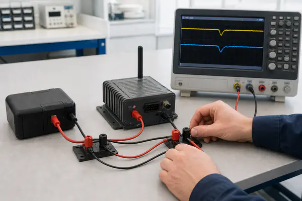
Engineers should capture current and voltage through a complete wireless event at both the battery and load 【7】, then compare the minimum with device thresholds. Include temperature, aging, retries, and realistic recovery intervals to separate battery limitations from other power-path losses.
What Should Be Measured During a Transmission Event?
- Battery open-circuit voltage before the event;
- Voltage directly at the battery terminals under load;
- Voltage at the modem or converter input;
- Peak current and pulse duration;
- Minimum load voltage and recovery time;
- Network-attempt count, battery temperature, and reset status.
An oscilloscope with a suitable current probe or characterized shunt is normally required. A digital multimeter remains useful for steady-state checks, but it can miss short IoT battery voltage drop events.
A Step-by-Step IoT Battery Voltage Drop Failure Analysis
- Record a successful transmission using a laboratory supply, then repeat with the intended battery.
- Probe the battery and load voltage simultaneously.
- Test normal and weak-signal conditions.
- Evaluate fresh and aged samples at minimum temperature.
- Check recovery and the maximum retry sequence.
- Compare results with modem and MCU limits.
- Verify the correction across multiple samples.
| Test condition | Measurement | Acceptance question |
|---|---|---|
| Room temperature, fresh source | Peak current and minimum load voltage | Does the device transmit without reset? |
| Minimum operating temperature | IoT battery voltage drop and recovery time | Is adequate voltage margin retained? |
| Aged or stored source | First-pulse response | Does passivation cause voltage delay? |
| Weak signal or retry sequence | Pulse count and radio-on time | Can the source recover between events? |
| Production interconnect | Battery-to-load voltage difference | Are connector and wiring losses acceptable? |
Rmax = (Vsource,min − Vload,min) / Ipeak
Temperature, aging, tolerances, wiring, dynamic impedance, and converter behavior require additional margin. This calculation is a screening tool, not a substitute for prototype testing.
Illustrative Engineering Failure Analysis
Consider a location-independent NB-IoT smart-meter example. The equipment operates normally in sleep mode but occasionally resets during data upload. Testing reproduces a public Texas Instruments load example of approximately 250 mA for 250 ms. 【4】 This is not LONGSING customer data.
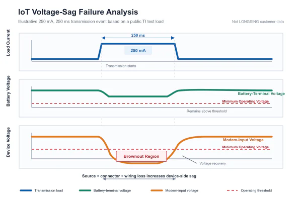
The cell-terminal voltage remains acceptable while the modem input crosses its brownout threshold. This reproduces the IoT battery voltage drop. Production interconnect resistance increases the difference, while repeated transmissions limit recovery. The cause is combined source, interconnect, and conversion resistance—not capacity alone.
Corrections may include reducing interconnect resistance, reviewing conversion, improving antenna or retry logic, adding suitable capacitance, evaluating a hybrid pulse capacitor, or changing chemistry. 【6】 Validate low temperature, aged sources, production tolerances, and maximum retries. See LONGSING’s IoT battery optimization strategies.
When Can a Hybrid Pulse Capacitor Reduce IoT Battery Voltage Drop?
A hybrid pulse capacitor can help when a device requires short current bursts that exceed the practical pulse capability of its long-life energy source. The HPC supplies part of the transient current and recharges between events. Suitability depends on voltage, impedance, capacity, pulse duration, frequency, temperature, and available recharge time.
How an ER + HPC System Shares Energy and Pulse Power
In an ER + HPC architecture, a bobbin-type Li-SOCl₂ cell provides long-duration energy at a comparatively low current. The rechargeable HPC acts as a pulse-support device during transmission and is replenished during standby.
This division can reduce current drawn directly from the primary cell, limit battery voltage sag, and help the system use more of the cell’s available energy. It does not eliminate losses, guarantee service life, or correct an unsuitable converter, antenna, firmware, or PCB design. Read the hybrid supercapacitor technical guide and review the ER26500 + HPC1520 IoT battery solution.
What Parameters Determine Whether an HPC Is Suitable?
Engineers should evaluate maximum voltage, HPC voltage before transmission, peak and continuous current, pulse duration, minimum load voltage, ESR, available capacity, recharge time, leakage, temperature, aging, mechanical size, and connection resistance.
HPC1520 vs HPC1530 vs HPC1550: What Should Engineers Compare?
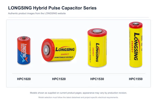
| Model | Maximum capacity | Maximum continuous discharge current | Resistance | Operating temperature |
|---|---|---|---|---|
| HPC1520 | 80 mAh | 500 mA | ≤160 mΩ | −40°C to +85°C |
| HPC1530 | 180 mAh | 800 mA | ≤110 mΩ | −40°C to +85°C |
| HPC1550 | 450 mAh | 2,000 mA | ≤60 mΩ | −40°C to +85°C |
These are public LONGSING product-page values, not universal pulse ratings. 【5】 Confirm the current product revision, voltage conditions, and application limits through the hybrid pulse capacitor product series and HPC technical specifications.
How Should a Custom ER + HPC Battery Pack Be Designed and Validated?
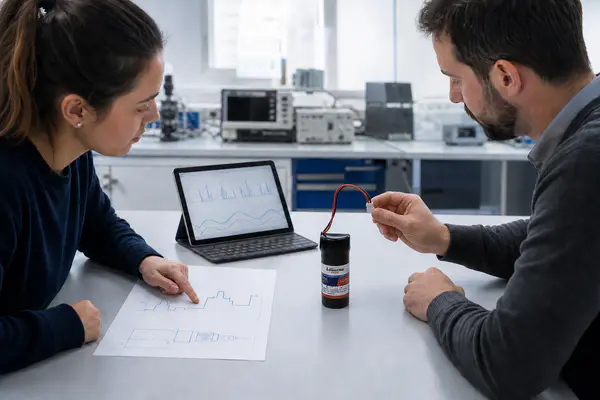
A custom ER + HPC pack should begin with the measured device load profile, not a battery model number. Electrical, environmental, mechanical, and regulatory requirements determine the cell, HPC, wiring, connector, protection, and test plan. Samples must then be validated under realistic temperature, aging, signal, and retry conditions.
What Information Does a Battery Supplier Need?
| Customer input | Engineering decision | Validation method |
|---|---|---|
| Voltage range and cut-off voltage | Series configuration and power architecture | Loaded-voltage test |
| Sleep and peak current | ER cell and HPC model | Current-profile capture |
| Pulse duration and interval | Pulse capacity and recovery requirement | Repeated transmission test |
| Temperature range | Component and material selection | Environmental testing |
| Mechanical envelope | Pack layout and insulation | Fit and vibration review |
| Wire and connector requirements | Interconnect resistance and assembly | Voltage-drop inspection |
From Load Profile to Prototype Pack
- Capture the actual device load profile.
- Define voltage and environmental limits.
- Select a primary cell and pulse-support component.
- Review wiring, connectors, protection, sealing, and mechanical requirements.
- Build representative samples.
- Test pulse response and recovery.
- Repeat at temperature and under aged conditions.
- Adjust the configuration where necessary.
- Establish production acceptance criteria.
What Should Be Verified Before Mass Production?
Qualification should confirm minimum load voltage, recovery time, temperature behavior, connector resistance, assembly consistency, physical fit, environmental protection, and compliance documentation. Testing should use production-representative wiring, connectors, firmware, antennas, and enclosures.
LONGSING can review device voltage, sleep current, peak current, pulse duration, transmission interval, protocol, temperature range, target life, mechanical limits, and connector requirements. Its engineering team can recommend an ER + HPC configuration, prepare samples, and conduct project-specific tests through its custom battery-pack development process. Final performance remains subject to application validation.
Conclusion
IoT battery voltage drop is a system-level problem involving the energy source, interconnects, converter, radio behavior, temperature, and firmware. Diagnosis requires measuring the real transmission waveform at both the battery and load. A hybrid pulse capacitor may support short high-current events when the base source cannot maintain voltage, but the ER + HPC configuration must be validated under the device’s actual operating conditions.
Frequently Asked Questions
Click to explore more information about IoT battery voltage drop and ER + HPC solutions
Q: Why does an IoT battery show normal voltage but fail during transmission?
A: Open-circuit voltage is measured under little or no load. Transmission current flowing through the power path can pull the modem or MCU input below its minimum operating voltage.
Q: What causes IoT battery voltage drop in NB-IoT devices?
A: Common causes include battery impedance, passivation, low temperature, aging, resistive interconnects, long wiring, converter losses, high transmission current, weak-signal operation, and repeated network attempts.
Q: Can a multimeter detect a short transmission-related voltage drop?
A: Usually not reliably. A multimeter may average or miss a brief pulse. Engineers normally use an oscilloscope and suitable current measurement to capture peak current and minimum load voltage.
Q: What is a hybrid pulse capacitor?
A: A hybrid pulse capacitor is a rechargeable pulse-support component designed to deliver and recover from short high-current events. In an ER + HPC pack, it complements the primary Li-SOCl₂ cell rather than replacing it.
Q: Is an HPC the same as a conventional supercapacitor?
A: No. Their energy-storage mechanisms, voltage behavior, capacity, leakage, ESR, and charging requirements can differ. Engineers should use the applicable HPC specification and validate it with the actual device load profile.
Q: How do engineers choose between HPC1520, HPC1530, and HPC1550?
A: Compare the system voltage, peak-current waveform, pulse duration, recovery interval, minimum temperature, ESR limit, required capacity, and mechanical space. Confirm the selection using the current datasheet and application testing.
Q: Can an HPC extend IoT battery life?
A: It may improve usable energy and reduce stress on the primary cell in pulsed applications. Service life also depends on standby current, transmission frequency, temperature, leakage, aging, network conditions, and firmware.
Q: What information is needed to develop a custom ER + HPC battery pack?
A: Provide the device voltage range, sleep current, peak current, pulse duration, transmission interval, wireless protocol, minimum operating voltage, temperature range, target service life, dimensions, wiring, connector, and validation requirements.
References
【1】Energy efficiency and UE power-saving context. ↪
【2】Li-SOCl₂ passivation and pulse-response context. ↪
【3】LTE-M and NB-IoT energy-consumption context. ↪
【4】Public 250 mA / 250 ms smart-meter test condition. ↪
【5】LONGSING HPC model specification context. ↪