
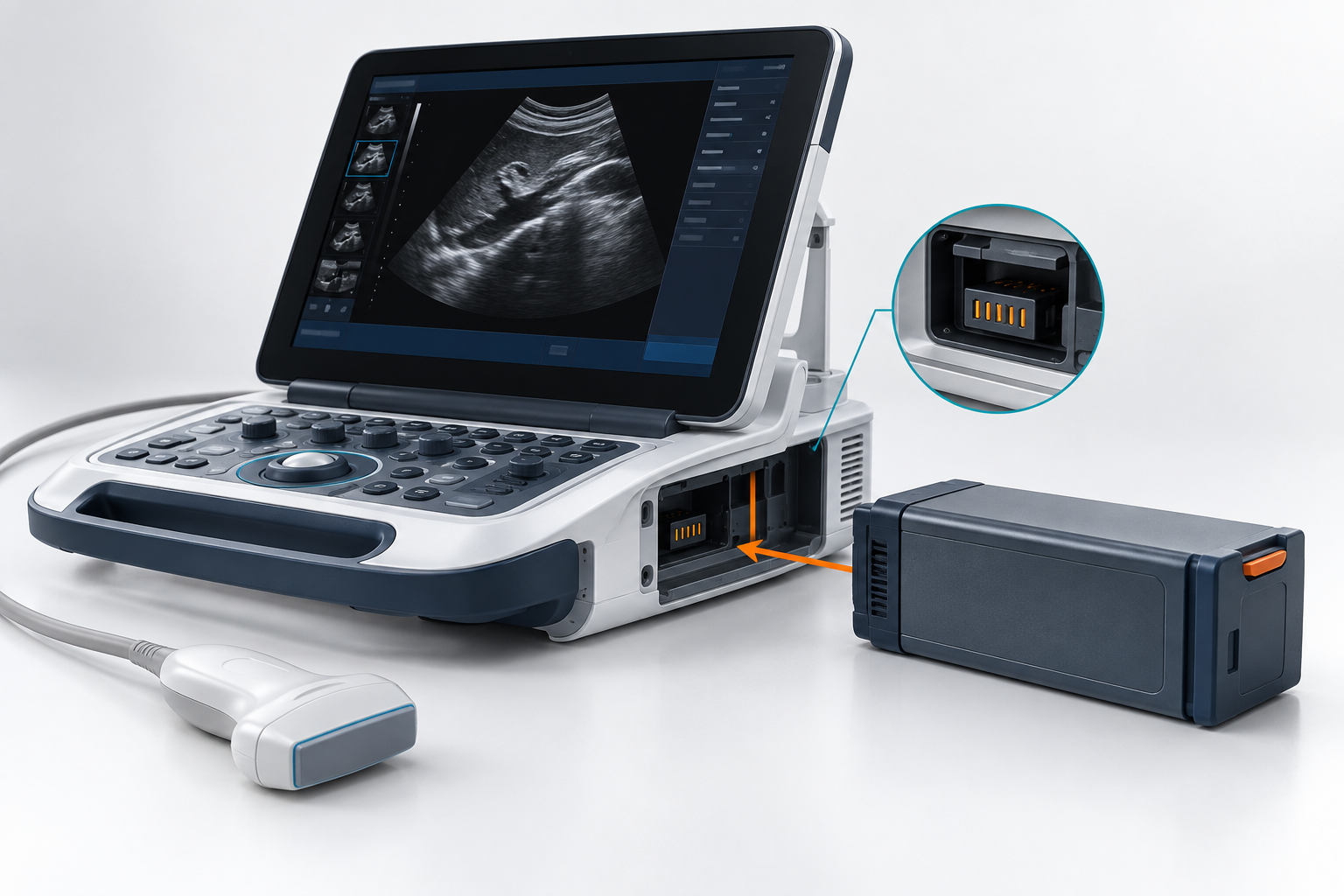
Portable ultrasound OEMs often begin with a target voltage and Ah rating. That is not enough. Runtime, peak load, available space, charging behavior, lifecycle targets and compliance constraints all affect pack architecture.
A reliable battery design starts from the complete device specification—not a preferred cell format or nominal capacity.
Featured Snippet: What Should a Portable Ultrasound OEM Specify Before Developing a Battery Pack?
A portable ultrasound OEM should specify the system voltage range, required runtime, average and peak power, usable battery energy, available dimensions, weight limit, charging method, operation-while-charging requirement, BMS and fuel-gauge needs, connector interfaces, operating temperature, cycle-life target and applicable safety requirements. These inputs determine the cell format, series/parallel configuration, charging architecture, protection system and mechanical battery-pack design.
Table of Contents
1. What Electrical Requirements Should a Portable Ultrasound OEM Define?
The electrical specification for a portable ultrasound battery pack should begin with the complete device power architecture, not a preferred battery voltage or Ah rating.
The OEM needs to define the voltage range the ultrasound system can accept, how much usable energy the intended workflow requires, and what continuous and transient loads the pack must support.
Define the System Voltage Window, Not Only Nominal Voltage
A request such as:
“We need a 7.4V battery.”
is not yet a complete battery specification.
The battery supplier also needs to know:
- Nominal battery voltage
- Maximum permitted input voltage
- Minimum operating voltage
- Internal DC-bus requirements
- DC/DC converter architecture
- Charger voltage architecture
- Whether the battery powers the device directly or through intermediate conversion stages
LONGSING provides rechargeable-pack directions such as 3.7V battery packs and 7.4V battery packs, but these are architecture examples rather than standard portable-ultrasound voltages.
For example, a 7.4V-class design may use a 2S lithium-ion configuration, while another ultrasound system may require a completely different battery bus. The correct series configuration should therefore follow the host device’s actual electrical architecture.
Calculate Runtime From Usable Energy, Not Nominal Ah
Battery capacity in amp-hours is useful, but Ah cannot be interpreted correctly without voltage.
Nominal Battery Energy (Wh) = Nominal Voltage (V) × Rated Capacity (Ah)
However:
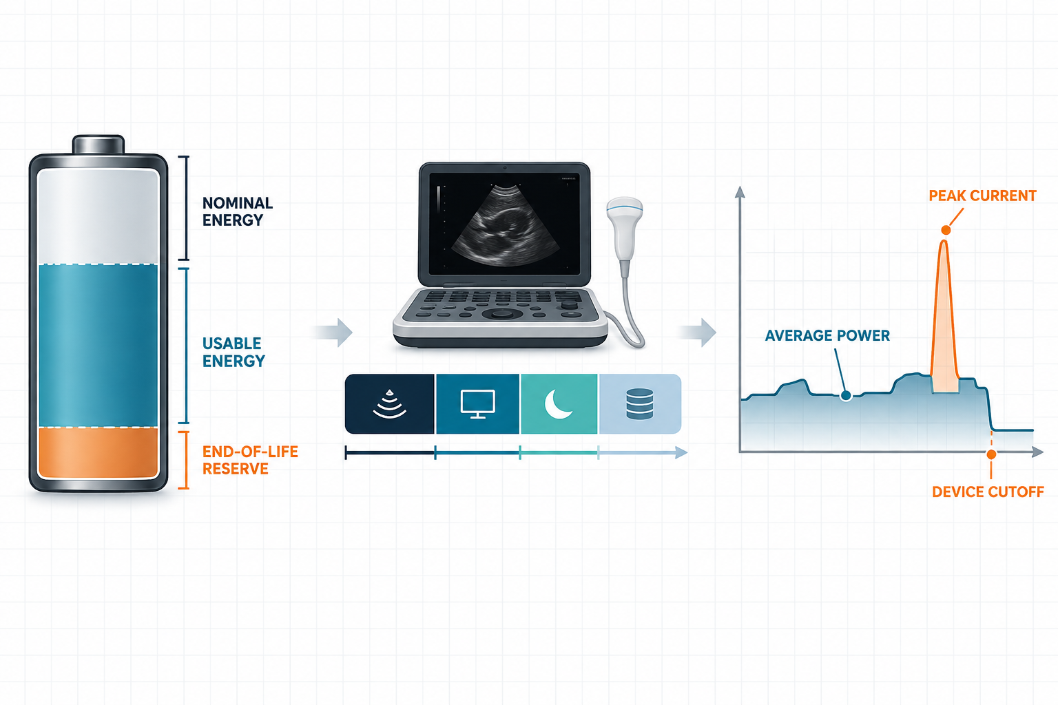
Nominal battery energy is not the same as usable system energy.
Usable energy can be affected by:
- Device minimum operating voltage
- BMS discharge cutoff
- Cell discharge characteristics
- DC/DC conversion efficiency
- Temperature
- Battery aging
- Required end-of-life reserve
A first-order runtime estimate is:
Estimated Runtime ≈ Usable Battery Energy ÷ Average Device Power
If the portable ultrasound operates in several distinct modes, a better model is:
Erequired = Σ(Pmode × tmode)
The duty cycle may include different combinations of:
- Active imaging
- Image processing
- Display operation
- Standby
- Data transfer
- User-interface activity
- Wireless communication where applicable
The battery supplier therefore benefits much more from a measured device-input power profile than from a statement such as “we need four hours of runtime.”
The useful specification is:
This is the device power profile under defined operating modes, and this is the required runtime.
Separate Average Power From Peak Current
Average power and transient current solve different battery-design problems.
Average power primarily affects required usable Wh, runtime, cell capacity and parallel capacity. Peak or transient current affects cell current capability, parallel configuration, voltage sag, BMS current thresholds, interconnections, cables and connectors.
A battery pack can contain enough energy for the required runtime and still be unsuitable if a transient system load produces excessive voltage sag or trips the BMS.
For this reason, OEMs should specify:
Peak current + pulse duration
rather than only:
Maximum current
A 5 A transient lasting tens of milliseconds presents a different battery requirement from a 5 A load sustained for several seconds.
Electrical Requirement Inputs
| Requirement | OEM Should Define | Why It Matters |
|---|---|---|
| System voltage | Nominal, maximum and minimum voltage | Determines series architecture |
| Runtime | Required operating time under defined modes | Determines usable-energy target |
| Average power | Measured or validated W | Drives long-term energy requirement |
| Peak load | Current + duration | Influences cells, BMS and interconnects |
| Device cutoff | Minimum acceptable device-input voltage | Defines usable voltage window |
| Reserve | Required end-of-life margin | Prevents optimistic runtime sizing |
The output of this stage should be a device-level electrical requirement, not simply a voltage and Ah target.
2. How Do Mechanical Space, Cell Format and Charging Architecture Affect the Pack?
Once the electrical requirement is known, the OEM and battery supplier can evaluate which physical battery architecture fits the ultrasound system.
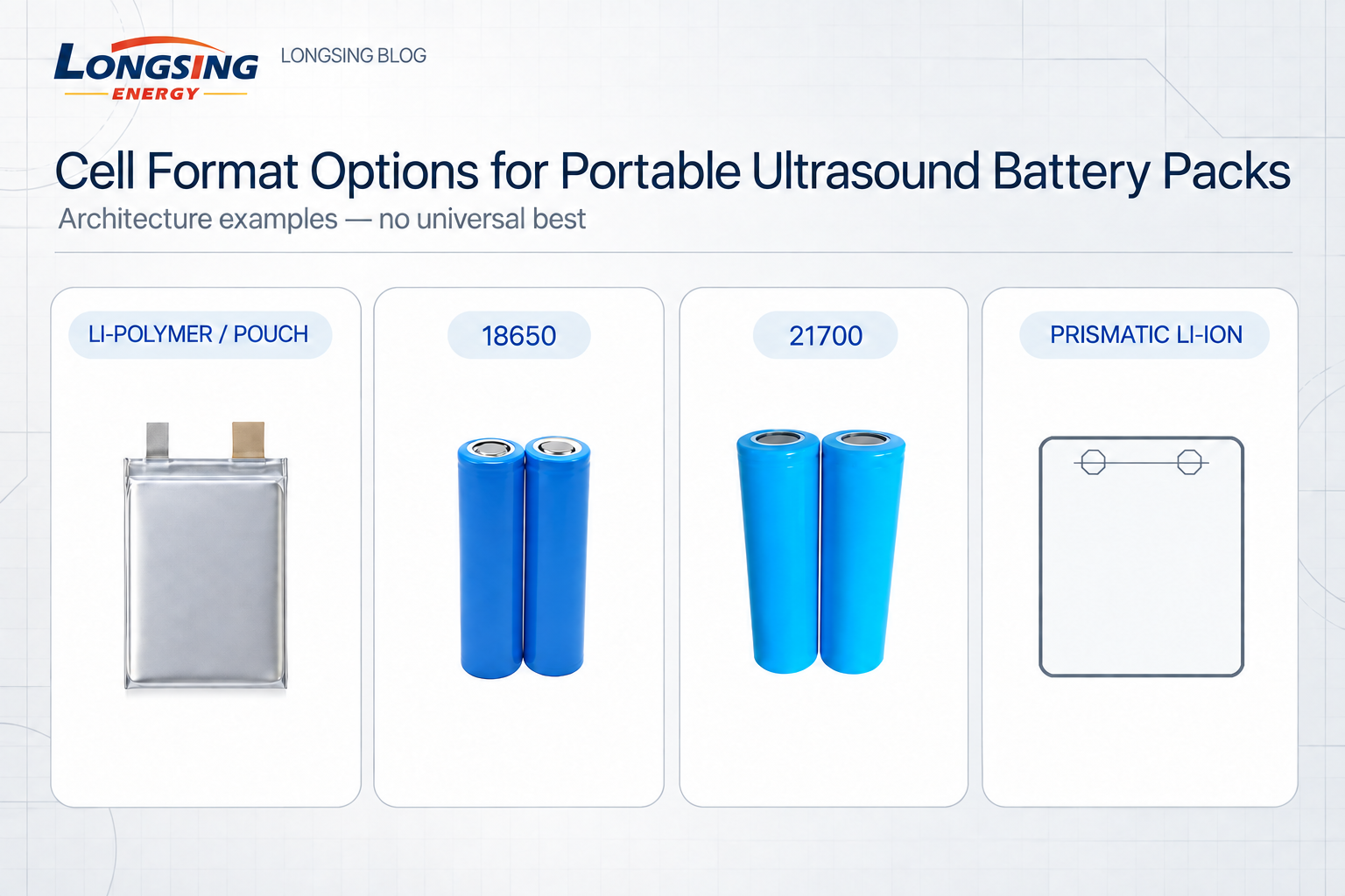
Li-polymer/pouch, 18650, 21700 and prismatic Li-ion cells can all be valid candidates. There is no universally best cell format for portable ultrasound equipment.
Evaluate Cell Format From the Complete Mechanical Envelope
Li-polymer / pouch cells can be evaluated when the device requires a thin battery section, low-profile packaging, application-specific dimensions, or tight weight and geometry constraints. Their suitability still depends on the specific cell design, electrical requirement, mechanical protection, dimensional-change allowance and thermal environment.
18650 cylindrical cells provide a standardized architecture and can be configured into different series/parallel arrangements. They may be worth evaluating when cylindrical cells fit the enclosure, smaller individual cells provide useful layout flexibility, and an appropriate S/P configuration can meet voltage, capacity and current requirements.
21700 cylindrical cells provide a larger cylindrical alternative. Depending on the selected cell and system requirements, the format can change physical cell count, parallel count, pack dimensions, interconnections, current capability and thermal layout. A larger cell does not automatically produce a better portable ultrasound battery pack.
Prismatic lithium-ion cells can be considered when the enclosure provides a defined rectangular battery space. Their geometry creates a different mechanical and thermal integration problem from cylindrical cells and may be useful when the compartment is compatible with larger flat cells.
For a deeper engineering comparison, see LONGSING’s 18650 vs 21700 vs Prismatic Cells guide and its broader lithium-ion battery guide.
Cell format should be selected at pack level.
Energy density, thermal performance, safety, lifecycle and system efficiency should not be ranked from cell shape alone.
Cell-Format Screening Questions
| Candidate Format | Potential Pack-Level Reason to Evaluate | Key Questions |
|---|---|---|
| Li-polymer / pouch | Thin or application-specific geometry | How will the pack provide protection, support and dimensional allowance? |
| 18650 | Cylindrical modularity and layout flexibility | How many cells, welds and interconnections are required? |
| 21700 | Potentially fewer physical cells for a target | Does the larger diameter improve or restrict the real enclosure layout? |
| Prismatic Li-ion | Rectangular battery compartment | How will restraint, thermal contact and expansion be managed? |
Specify More Than Length × Width × Height
A battery supplier needs more than the maximum external dimensions. Useful mechanical inputs include:
- Maximum length × width × height
- Permitted battery shape
- Weight limit
- Mounting orientation and mounting points
- Internal or removable battery
- Connector position and cable-exit direction
- Required clearance
- Shock and vibration requirements
- Service and replacement method
The nominal battery volume may also need to accommodate BMS electronics, harnesses, connectors, insulation, cell supports, protective structures and thermal interfaces.
The battery should be integrated into the product architecture early—not designed around whatever empty space remains near the end of development.
Connector and Cable Requirements Affect Electrical Performance
Battery electrical performance does not stop at the cell terminals.
Cells → interconnections → BMS → cable → connector → ultrasound device
Each element introduces resistance, and the resulting voltage drop follows:
Vdrop = I × R
The OEM should specify the connector family or mating interface, maximum expected current, cable length, wire-size constraints, pinout, thermistor connections, identification or communication pins, and retention or locking requirements.
The final design should verify the voltage available at the ultrasound device input, not merely at the cell or pack terminals.
Define the Charging Architecture Before Finalizing the Battery Pack
A requirement such as “USB charging” or “adapter charging” is still incomplete. The OEM should define:
- Input source and maximum available input power
- Target charging time
- Charger location
- Whether charging control resides in the host, battery pack or external charger
- Battery temperature sensing
- Removable or internal battery architecture
- Charging behavior at abnormal temperatures
One particularly important question is:
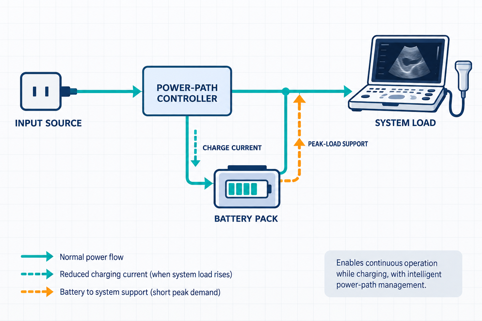
Can the portable ultrasound device operate while the battery is charging?
Operation While Charging Requires Power-Path Planning
If the device must operate and charge simultaneously, the charging system may have to manage available input-source power, ultrasound system load, battery charging current, input-current limits, battery supplementation during peak demand and thermal conditions.
A common dynamic power-path management principle is to prioritize maintaining the system rail and reduce the battery charge current when host load increases. [8]
This is an engineering principle, not a recommendation for one specific charger IC.
Operation while charging is a system power requirement—not simply a charger setting.
It can also create a more demanding thermal condition because the device may simultaneously generate heat from imaging and processing electronics, power conversion, charger electronics and battery charging. The assembled device should be evaluated under this combined operating condition.
3. What BMS, Thermal and Lifecycle Requirements Should Be Specified?
A custom battery pack for a medical device requires more than cells connected to a protection board.
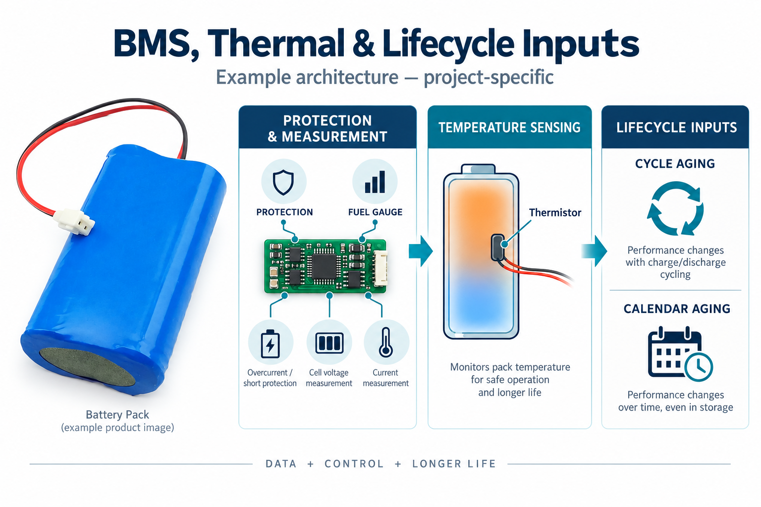
The OEM should define the protection functions, battery-state information, interfaces, thermal requirements and lifecycle target before the final BMS and cell architecture are selected.
Specify Protection Functions Instead of Only “Smart BMS”
For a specific portable ultrasound project, the OEM should define which battery-management functions the device actually needs. Possible requirements include:
- Overcharge and overdischarge protection
- Overcurrent and short-circuit protection
- Charge-temperature and discharge-temperature protection
- Cell-voltage and pack-current monitoring
- Cell balancing for applicable multi-series architectures
The thresholds and response behavior must match the selected cells, charger, load, host-system voltage limits and required fault behavior. A medical application does not automatically require a complex communication BMS.
Decide Whether Fuel Gauging Is Required
Protection and fuel gauging are different functions.
If the ultrasound interface needs to display battery percentage, a low-battery warning, remaining operating time or state-of-health information, the requirement should be defined early.
Depending on the architecture, battery-state estimation can use combinations of voltage, current integration, temperature, a cell model, learned capacity and aging information.
An OEM that specifies only “BMS required” may receive a protection solution without the battery-state information expected by the device user interface. A better RFQ states the required SOC accuracy, remaining-runtime behavior and host communication requirements.
Define Battery Communication and Interface Requirements
If the host needs battery data, the OEM should specify the actual interface. Possible approaches include thermistor lines, analog identification, dedicated status outputs, I²C, SMBus, UART or another defined interface.
Communication should follow the host architecture. There is no reason to add a particular protocol automatically simply because the battery is intended for medical equipment.
Define Charging and Discharging Temperatures Separately
One generic “operating temperature” specification is usually insufficient. OEMs should define:
- Charging temperature range
- Discharging temperature range
- Storage temperature range
- Expected battery-zone temperature inside the assembled device
A portable ultrasound enclosure can contain heat-producing display electronics, processors, power converters, charging circuits and ultrasound transmit/receive electronics. The battery can therefore experience a different environment from the surrounding room.
What temperature does the battery actually experience during the device’s defined operating and charging modes?
That is the relevant design question—not simply the hospital room temperature.
Define Cycle Life With Test Conditions
A lifecycle requirement such as “500 cycles minimum” is incomplete.
A 2025 peer-reviewed lithium-ion aging review identifies temperature, charge/discharge rate, depth of discharge and state of charge among the important factors influencing capacity fade. [6]
A better lifecycle requirement is:
X cycles to Y% retained capacity under defined charge rate, discharge rate, depth of discharge, voltage and temperature conditions.
The OEM should consider specifying target cycle count, end-of-life retained capacity, charge rate, discharge rate, depth of discharge, upper charging voltage, test temperature and typical usage pattern.
Include Calendar Aging and Standby Behavior
Calendar aging should also be considered. A device that remains connected to external power or spends extended periods at high state of charge can experience a different degradation pattern from a battery evaluated only by cycle count.
A peer-reviewed review of commercial lithium-ion calendar aging reports that storage temperature and voltage/state of charge strongly influence calendar degradation, with the magnitude depending on the cell chemistry and construction. [7]
For portable ultrasound equipment, the lifecycle discussion should therefore include:
- Expected time at high SOC
- Time connected to the charger or dock
- Standby and storage temperature
- Use frequency and cycle depth
- Required capacity after the intended service interval
BMS, Thermal and Lifecycle Inputs
| Area | OEM Input | Design Impact |
|---|---|---|
| Protection | Required faults, thresholds and recovery behavior | Defines BMS protection architecture |
| Fuel gauge | SOC accuracy, runtime display and warning behavior | Defines sensing, algorithm and calibration needs |
| Communication | Thermistor, ID, I²C, SMBus, UART or other interface | Defines host/BMS integration |
| Temperature | Charge, discharge, storage and internal battery-zone ranges | Influences cells, protection and thermal design |
| Cycle life | Cycles, retained capacity and controlled test conditions | Enables measurable lifecycle validation |
| Calendar life | Service interval, docked time, SOC and storage conditions | Prevents cycle-only lifetime assumptions |
4. What Safety, Validation and RFQ Information Should Medical Device OEMs Prepare?
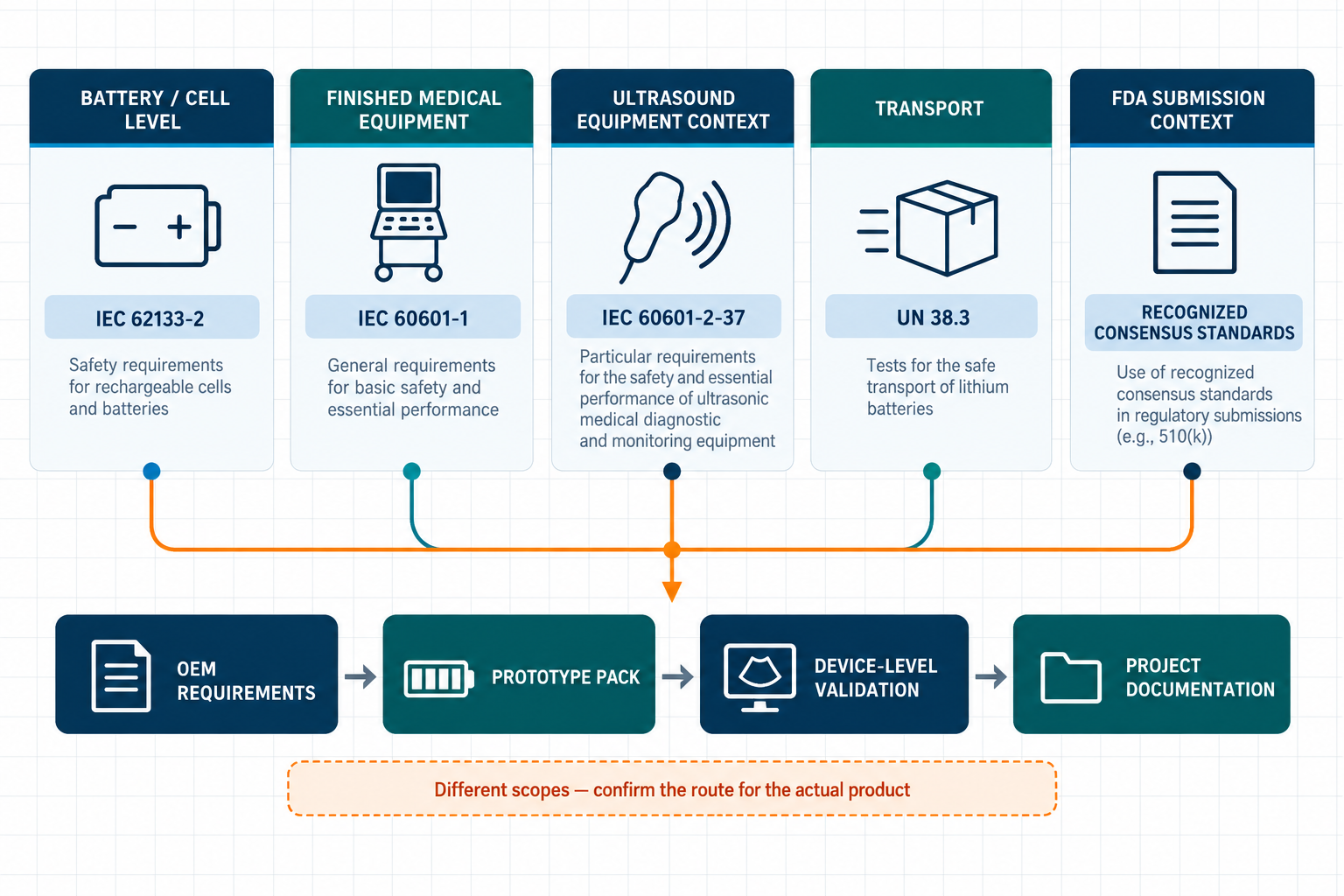
Portable ultrasound battery development involves several different safety and compliance layers. These layers should not be merged into one claim.
Keep Battery, Medical-Equipment, Transport and Regulatory Boundaries Clear
IEC 62133-2:2017+A1:2021 addresses safety requirements and tests for portable sealed secondary lithium cells and batteries. It is relevant at the cell/battery level; it is not a complete medical-device standard. [1]
IEC 60601-1 Edition 3.2 addresses general requirements for the basic safety and essential performance of medical electrical equipment. It applies in the context of the finished medical equipment, not as a generic battery-pack certification label. [2]
IEC 60601-2-37:2024 contains particular requirements for ultrasonic medical diagnostic and monitoring equipment. It belongs to the finished-equipment context and does not replace battery-level evaluation. [3]
UN Manual of Tests and Criteria, subsection 38.3 concerns transport testing for lithium cells and batteries. UN 38.3 supports transport qualification; it does not establish medical-device safety or approval. [4]
The FDA Recognized Consensus Standards database identifies voluntary consensus standards recognized by the FDA for medical-device submissions. Recognition of a standard can support a conformity strategy, but it does not mean that a generic battery pack is “FDA approved” or that the finished device is approved automatically. [5]
Accordingly, a supplier should not claim a universal medical certification, an “FDA-certified battery,” or an “IEC 60601-certified battery” without project-specific and current evidence.
Validation Should Follow the Real Device Use Case
Documentation and component selection are only part of the engineering work. Prototype and system validation should reproduce the actual electrical, mechanical, thermal and charging conditions of the finished portable ultrasound device.
Useful validation conditions can include:
- Active imaging at representative and worst-case load
- Maximum specified continuous load
- Defined transient-current events
- Low-temperature and high-temperature operation
- Charging at the allowed temperature limits
- Operation while charging, if required
- End-of-discharge and aged-battery conditions
- Connector and cable voltage drop
- Fault response and recovery behavior
- Mechanical fit, retention, shock and vibration
Portable Ultrasound Battery Validation Matrix
| Validation Area | Example Condition | What to Confirm |
|---|---|---|
| Runtime | Representative workflow and duty cycle | Required operating time with defined reserve |
| Peak load | Worst specified current waveform | No unacceptable sag, reset or BMS trip |
| Thermal | Imaging, charging and combined operation | Cell and pack temperatures remain within limits |
| Lifecycle | Defined cycle and calendar-aging conditions | End-of-life capacity and resistance targets |
| Interface | Production cable, connector and host input | Voltage, retention, pinout and communication |
| Mechanical | Installed pack, shock and vibration | Fit, restraint, insulation and serviceability |
| Safety | Applicable abnormal and fault conditions | Protection behavior and project-specific evidence |
What Should Be Included in the Battery RFQ?
A useful RFQ should make the application requirements measurable before a cell or pack is proposed.
| RFQ Category | Information to Provide |
|---|---|
| Electrical | Nominal/minimum/maximum voltage, average power, peak current and duration, device cutoff |
| Runtime | Required hours under defined device modes and end-of-life reserve |
| Mechanical | Maximum dimensions, shape, weight, mounting, connector location and service method |
| Charging | Input source, power limit, charge time, charger location and operation-while-charging requirement |
| BMS | Protection functions, thresholds, recovery, balancing, SOC and communication |
| Thermal | Charge/discharge/storage ranges and internal battery-zone temperature |
| Lifecycle | Cycle-life and calendar-life targets with test conditions |
| Compliance | Target markets, applicable standards and required project documentation |
| Validation | Device-level test plan, sample stages and acceptance criteria |
Where LONGSING Fits
LONGSING’s lithium-ion battery pack range provides a starting point for evaluating rechargeable pack architectures. Relevant internal resources include:
- 3.7V Battery Packs
- 7.4V Battery Packs
- Li-Polymer Batteries
- 18650 Batteries
- 21700 Batteries
- 3.7V Li-Ion Prismatic Batteries
These are architecture options, not a claim that one voltage or cell format is standard for ultrasound equipment. Final feasibility, compliance evidence and validation should be confirmed for the actual project.
Conclusion
A reliable portable ultrasound battery pack cannot be specified from voltage and Ah alone. The OEM should define the complete device voltage window, usable-energy requirement, average and peak loads, mechanical envelope, charging behavior, BMS and fuel-gauge needs, thermal conditions, lifecycle targets and applicable safety requirements.
There is no universal best choice among Li-polymer, 18650, 21700 and prismatic lithium-ion cells. Likewise, 3.7V and 7.4V are possible architecture examples—not ultrasound standards.
The correct battery architecture is the one that meets the finished device’s electrical, mechanical, thermal, lifecycle, transport and medical-equipment requirements under validated operating conditions.
Discuss Your Portable Ultrasound Battery Requirements
Developing a portable ultrasound system or another rechargeable medical device?
Provide the system voltage range, measured load profile, required runtime, peak-current waveform, available battery dimensions, weight target, charging architecture, operation-while-charging requirement, connector and communication interfaces, battery-zone temperature, cycle/calendar-life target, intended markets and validation requirements.
These inputs allow candidate custom lithium battery pack architectures to be compared against the actual device rather than against a generic voltage and capacity label.
Frequently Asked Questions About Portable Ultrasound Battery Packs
Click to explore more information about portable ultrasound battery pack design
Q: What information is needed to design a portable ultrasound battery pack?
A: Define the accepted voltage range, required runtime, average and peak power, usable energy, device cutoff, dimensions, weight, charging method, operation-while-charging requirement, BMS and fuel-gauge functions, connector interface, temperature ranges, lifecycle target and applicable safety requirements.
Q: Is 7.4V a standard voltage for portable ultrasound equipment?
A: No. A 7.4V-class pack is one possible 2S lithium-ion architecture, not a universal ultrasound standard. The correct battery voltage must follow the host device’s DC bus, charger and power-conversion architecture.
Q: How should battery runtime be calculated for portable ultrasound?
A: Calculate the required energy from the measured power and duration of each operating mode, then account for conversion losses, device cutoff, BMS cutoff, temperature, aging and end-of-life reserve. Nominal Ah alone is not an adequate runtime specification.
Q: Which cell format is best for a portable ultrasound battery?
A: There is no universal best format. Li-polymer, 18650, 21700 and prismatic Li-ion cells should be compared at pack level against electrical load, runtime, dimensions, weight, thermal conditions, lifecycle, manufacturing and safety requirements.
Q: Can a portable ultrasound device operate while its battery is charging?
A: It can if the host power architecture is designed and validated for simultaneous operation and charging. The system must manage input-source power, device load, charge current, battery supplementation, thermal conditions and charge termination behavior.
Q: Does a medical-device battery always need a smart BMS?
A: Not automatically. The required BMS depends on protection thresholds, series count, balancing, sensing, SOC accuracy, remaining-runtime display and host communication. Protection and fuel gauging should be specified as separate functions.
Q: Which standards can apply to a portable ultrasound battery project?
A: IEC 62133-2 can be relevant at the portable lithium cell and battery level; IEC 60601-1 and IEC 60601-2-37 belong to the finished medical-equipment context; and UN 38.3 addresses transport testing. The actual route depends on the product, market and project scope.
Q: Does FDA recognition of a standard mean the battery or finished ultrasound device is FDA approved?
A: No. FDA recognition identifies voluntary consensus standards that may support medical-device submissions. It is not a generic approval of a battery pack and does not automatically establish approval of the finished device.