Humanoid robots fail when energy design is treated as an accessory. A weak pack causes voltage sag, motor faults, short runtime, and unsafe heat.
A well-modeled humanoid robot power system turns battery chemistry, BMS logic, motor load, and power conversion into one controlled engineering platform.
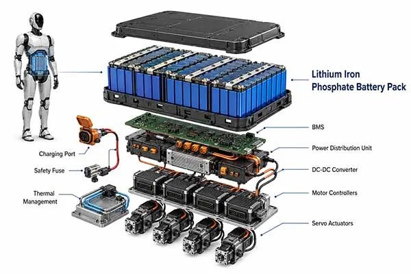
Humanoid robot power systems rely on a high-energy battery pack, intelligent BMS, DC/DC converters, motor drivers[1], sensors, and real-time communication. The main challenge is not only storing energy, but also delivering stable voltage and peak current while the robot walks, lifts, balances, calculates, and recovers motion energy.

A practical solution starts with power architecture, load modeling, and battery validation before the robot enters batch production.
Table of Contents
- What powers a humanoid robot?
- Why Power Is a Bottleneck for Humanoid Robots?
- How to Choose a Humanoid Robot Power Solution?
What powers a humanoid robot?
A humanoid robot is powered by a battery pack, BMS, power distribution unit, DC/DC converters, motor controllers, embedded computers, sensors, and communication buses.
The battery is the main robot power source, but the complete robot power system must manage voltage, current, heat, safety, and communication at the same time.
Power Architecture & Power Distribution Design
A humanoid robot power architecture usually starts from a 48 V, 52 V, or 72 V battery bus. This bus feeds high-power joint actuators, hip motors, knee motors, arm motors, end-effectors, AI computing boards, cameras, LiDAR[2], cooling fans, and safety controllers.
A stable robot power supply must separate high-current loads from low-noise control circuits, because a 120 A motor pulse can disturb a 5 V sensor rail if grounding, filtering, and bus impedance are not designed correctly.
In one anonymized project for a robot manufacturing factory in China, the customer used a 14S8P NMC cylindrical pack for a warehouse humanoid prototype. The nominal specification was 51.8 V, 38.4 Ah, about 1.99 kWh.
The first prototype showed random shutdown during squat-to-stand motion. Our failure analysis found that the humanoid robot power demand was highly coupled with voltage, motor power, joint load, and BMS protection thresholds. The pack voltage dropped from 51.2 V to 44.8 V during a 110 A peak load, and the motor controller recorded undervoltage faults.
The solution was not simply “use a larger battery”. The team changed cell grading, busbar thickness, nickel strip structure, BMS current sampling, and pre-charge[3] logic.
After matching cells by capacity, OCV, and ACIR, the parallel group voltage deviation was reduced from 42 mV to 13 mV after dynamic cycling. The improved robot power source held 47.6 V under the same load.
This case showed why humanoid robot power design must be validated inside the robot, not only on a battery tester.
| Power Layer | Typical Voltage | Main Load | Engineering Risk | Design Response |
|---|---|---|---|---|
| Main battery bus | 48–72 V | Joint motors, PDU | Voltage sag under peak torque | Low-resistance pack, matched cells, high-current BMS |
| Auxiliary rail | 12–24 V | Fans, brakes, pumps | Noise coupling | Isolated DC/DC and EMI filtering[4] |
| Logic rail | 5 V / 3.3 V | MCU, sensors, encoders | Reset during motor peaks | Separate grounding and local capacitance |
| AI compute rail | 12–19 V | GPU, camera hub | Thermal throttling | Efficiency-focused converter and thermal path |
Basal Power Consumption vs. Dynamic Peak Loads
Basal power is the energy needed when the robot stands, senses, computes, communicates, and performs small posture corrections. Dynamic peak load appears when the robot starts walking, climbs stairs, lifts a box, catches balance, or brakes a joint.
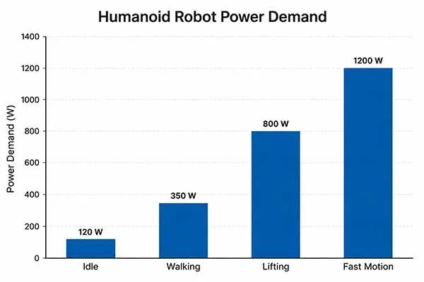
The same humanoid robot battery can look sufficient under a steady 500 W test, but fail during a 3,000 W joint acceleration event. That is why humanoid robot power modeling must combine average energy and transient current.
A simplified model is useful during early design:
Runtime ≈ Pack Energy × Usable DoD × System Efficiency ÷ Average Power
For example, a 51.2 V 20 Ah LFP pack stores about 1,024 Wh. If usable depth of discharge is 85% and total system efficiency is 90%, the usable energy is about 783 Wh. At 800 W average consumption, runtime is about 0.98 hour. At 1,200 W average consumption, runtime falls to about 0.65 hour.
This explains why many humanoid robots operate for only 1–2 hours when they walk continuously.
| Operating Mode | Estimated Power | Engineering Meaning | Battery Design Impact |
|---|---|---|---|
| Idle standing | 250–500 W | Compute, sensors, posture control | Low self-heating and stable low-current accuracy |
| Normal walking | 700–1,500 W | Continuous actuator demand | Energy density and heat balance |
| Lifting or stair motion | 2,000–4,000 W peak | Short high-torque events | Peak current margin and low internal resistance |
| Emergency recovery | 3,000 W+ peak | Balance correction | BMS response time and protection tuning |
A robot power supply must also handle peak current. If the robot requires 3 kW peak at 51.2 V, the pack current is about 58.6 A before conversion loss. With converter and wiring loss, the BMS should be rated higher, often 80–120 A continuous and 150–250 A peak, depending on the motion profile.
For a high discharge rate battery for robots, the discharge rating, thermal design, and connector resistance must be validated together.
Need High-Density Cells for Compact Ribcages?
Custom 300Wh/kg cells optimized for robotic space constraints.
Why Power Is a Bottleneck for Humanoid Robots?
Power is a bottleneck because humanoid robots need high torque, high compute load, long runtime, low weight, fast charging, and safe operation in the same machine.
Energy density, discharge rate, heat, voltage stability, and BMS communication must work together, or the robot loses performance before the battery is empty.
Current Energy Challenges in Humanoid Robotics
The central contradiction is simple: the robot needs more energy, but it cannot carry unlimited weight.
A larger humanoid robot battery improves runtime, yet extra mass increases joint torque, which then increases power consumption again. This loop is the main humanoid robot power challenge. A 10 kg pack may support longer operation, but if it increases hip and knee loading, the robot may consume more energy per meter walked.
Tips
The solution for the contradiction between weight and battery life:
1. Choose the right cell chemistry selection(such as LiFePO4);
2. Improve system efficiency(reducing motor-drive loss, improving actuator efficiency, and optimizing the voltage platform)
3. Allow operational strategy(swappable battery system or autonomous charging dock).
For a Japanese service humanoid project, the customer needed a quiet, safe, removable pack for indoor reception and facility guidance. The standard model we proposed was a 51.2 V 20 Ah LFP prismatic module, internally named LS-LFP51.2V20Ah-Robot.
The complete integration included a battery pack, smart BMS, insulated enclosure, sliding rail, blind-mate connector, pre-charge circuit, 24 V auxiliary output, CAN communication[5], LED service indicator, and docking charger. This power supply for robot applications focused less on maximum energy density and more on safety, cycle life, and predictable maintenance.
Humanoid Power Schemes by Application Scenario
| Application Scenario | Primary Constraints | Optimal Battery Chemistry & Pack Config | Target Voltage Platform |
| Industrial / Warehousing (High lifting, 8hr+ runtime) | High continuous torque, rapid hot-swapping required | High-capacity NMC cells, reinforced aluminum casing for forklift environments | 96V – 120V (Lowers current to reduce heat in high-power motors) |
| Disaster Response / Outdoors (Uneven terrain, impact risks) | Extreme structural vibration, thermal runaway containment | Semi-solid state or high-safety NMC with aerogel thermal barriers | 48V – 72V (Fuses safety with high instantaneous pulse power) |
| Domestic / Commercial Service (Close human interaction) | Low acoustic noise, strict thermal limits (<45℃ surface temp) | LFP or high-stability NMC with phase-change material (PCM) cooling | 24V – 48V (Safe, low-voltage touch-safe thresholds) |
The customer first expected two full hours of continuous walking from one small pack. The power audit showed that average load was closer to 900–1,100 W when the robot moved, talked, displayed content, and processed camera data.
The realistic operating time was 45–60 minutes from one 1 kWh pack. The final solution used a two-pack rotation plan and a docking charge station, because the industrial pain point was not only energy storage; it was service uptime.
| Challenge | Common Symptom | Root Cause | Practical Solution |
|---|---|---|---|
| Short runtime | Only 1–2 hours of operation | High average actuator and compute load | Accurate duty-cycle model and swappable pack |
| Heavy battery | Higher joint current | Energy density and payload conflict | NMC for compact energy or LFP for safer service duty |
| Voltage sag[6] | Motor driver fault | Cell IR, busbar loss, connector resistance | Low-impedance pack and dynamic load testing |
| Heat buildup | BMS derating | High RMS current and enclosure limits | Thermal path, spacing, and current margin |
Intelligent BMS and Protocol Integration for Physical AI
An intelligent BMS does more than protect against overcharge and overdischarge.
In a physical AI machine, the BMS must report voltage, current, cell temperature, SoC, SoH, SoF, alarms, and power limits to the robot controller. A modern humanoid robot power system should allow the motion planner to know whether the robot can climb stairs, lift a payload, or return to dock before the pack reaches a protection boundary.
Humanoid Robot Power System Decision Tree
| Engineering Question | Suggested Power System Direction |
| Need 8 hours of continuous work? | Use higher-capacity modular packs, swappable battery design, or charging dock strategy. Avoid relying only on one oversized pack. |
| Is joint space extremely limited? | Use compact cylindrical or pouch-cell layout, customized pack shape, high-density wiring, and distributed battery modules. |
| Does the robot work near humans? | Prioritize safer BMS logic, thermal protection, mechanical insulation, impact-resistant enclosure, and conservative discharge limits. |
| Does the robot require multi-joint high-speed coordination? | Select high-discharge cells, low-resistance busbars, fast BMS response, and pulse-load validation. |
| Is the robot mainly indoor and low-speed? | Prioritize energy density, cycle life, quiet thermal design, and maintenance convenience. |
| Does the robot lift objects or climb stairs? | Design for peak power, voltage sag resistance, heat dissipation, and reinforced connectors. |
| Is fast charging required? | Choose cells that support higher charge rates, add thermal sensing, and validate charger-BMS communication. |
| Is batch production planned? | Build a cell grading, pack assembly, aging test, and traceability process before mass production. |
For industrial deployment, we usually define three power limits.
The first is continuous discharge power, such as 2 kW for walking and light manipulation. The second is short peak power, such as 4 kW for 5–10 seconds. The third is safe fallback power, such as 500 W, which lets the robot stop, kneel, or dock safely.
This approach makes the robot power supply part of the motion-control strategy.
Power electronics also matter. GaN and SiC[7] devices can reduce switching loss in high-frequency DC/DC converters, especially when the system must convert the main battery bus into 24 V, 12 V, and compute rails.
A converter improvement from 94% to 97% efficiency may look small, but at 500 W auxiliary load, the heat loss drops from 30 W to 15 W. In a sealed torso, that 15 W reduction can protect both electronics and battery life.
| BMS Function | Data Output | Robot-Level Use | Failure Prevented |
|---|---|---|---|
| Cell monitoring | Cell voltage and temperature | Pack balancing and thermal warning | Cell drift and hot spot |
| Current sensing | Charge and discharge current | Power limiting and torque planning | Overcurrent shutdown |
| SoF calculation | Available peak power | Motion permission decision | Unsafe lift or stair attempt |
| CAN protocol | Fault codes and pack status | Robot controller integration | Blind operation under battery fault |
Real-Time State Estimation SoC SoH SoF via CAN EtherCAT
SoC tells the robot how much energy remains. SoH tells the maintenance team how much the pack has aged. SoF tells the controller how much power is available right now.
In a humanoid robot power system, SoF[8] is often the most important number during motion, because a pack at 40% SoC may still be safe for standing but unsafe for high-torque lifting if temperature is high or internal resistance has increased.
| State Metric | Meaning | Typical Input | Control Decision |
|---|---|---|---|
| SoC | Remaining charge | Current integration and OCV | Return-to-dock timing |
| SoH | Battery aging status | Capacity fade and resistance rise | Maintenance replacement |
| SoF | Available power | Voltage, temperature, resistance, current limit | Torque permission and safety fallback |
| Fault status | Protection condition | BMS alarm map | Stop, derate, or isolate pack |
A useful estimation structure combines coulomb counting, open-circuit voltage correction, impedance tracking, and temperature compensation.
The BMS can send the result through CAN, while EtherCAT[9] controls high-speed motor synchronization. The BMS does not need to replace EtherCAT; it needs to provide reliable energy-state data so the robot controller can make safe decisions.
In advanced designs, a robotics power management IC can improve rail supervision, sequencing, and fault reporting at the board level.
Motor and mechanical design also change energy demand. A better motor reduction ratio can reduce continuous current during standing and walking, but too high a ratio may reduce backdrivability and limit natural motion.
Kinetic energy recovery can return part of braking energy during downhill walking or joint deceleration, but it is not a magic solution. In practical service robots, recovered energy may improve usable runtime by 5–12% under favorable duty cycles.
Tips
Regenerative energy recovery can improve system efficiency, but it should be treated as a supporting strategy rather than the main solution to humanoid robot runtime.
To power humanoid robots efficiently, the system must combine battery design, converter efficiency, motor gearing, and motion control.
Facing Runtime, Heat, or Voltage Drop Issues?
We help robot teams balance energy density, discharge power, safety, and pack consistency.
How to Choose a Humanoid Robot Power Solution?
Choose a humanoid robot power solution by matching chemistry, voltage, capacity, discharge rate, BMS communication, mechanical enclosure, thermal path, and production consistency to the robot’s duty cycle. The best solution is not the largest battery; it is the safest pack that supports real load profiles with repeatable performance.
Battery Specification, Validation, and Production Consistency
A good selection process starts with a duty-cycle file.
The engineering team should record standing power, walking power, lifting peak current, recovery current, compute load, fan load, ambient temperature, allowed pack weight, target runtime, and safety certification needs. This file decides whether the project needs NMC cylindrical cells, LFP prismatic cells, or a hybrid pack strategy.
As a lithium ion battery manufacturer, we usually treat the battery specification as an engineering interface document, not a simple product catalog.
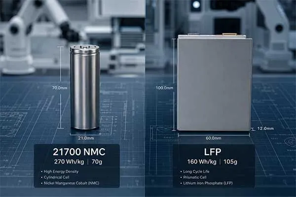
For compact mobile robots, NMC cylindrical packs may provide higher gravimetric energy density. For indoor service robots, LFP prismatic packs can provide stronger thermal stability, long cycle life, and easier maintenance.
A lithium ion battery for robotics project should also define vibration, drop, connector insertion cycles, enclosure fire resistance, and pack-level communication. A lithium ion battery for robot testing process should include static capacity, dynamic pulse, thermal cycling, BMS fault injection, CAN message verification, and robot-mounted endurance testing.
At Long Sing Energy, our engineer Jack Song and sales manager Luke Liu usually push customers to test the robot power source under real motion rather than only on a bench load. For batch production, the most important step is consistency control.
In one Chinese factory case, we used cell incoming inspection, ACIR grading, OCV aging, capacity sorting, weld resistance testing, EOL discharge testing[10], and QR-code traceability. The production data reduced pack capacity variation from about ±3.5% to ±1.2% across the pilot batch.
| Selection Item | NMC Cylindrical Pack | LFP Prismatic Pack | Best-Fit Scenario |
|---|---|---|---|
| Energy density | Higher | Moderate | NMC for compact mobile runtime |
| Thermal stability | Requires stricter control | Stronger | LFP for indoor service safety |
| Cycle life | Medium to high | High | LFP for daily docking cycles |
| Peak discharge | Strong with proper cell choice | Strong with proper pack design | Depends on motor peak current |
| Common robot format | 14S/16S cylindrical module | 16S 51.2 V module | Depends on voltage bus and enclosure |
A complete humanoid robot battery solutions package should include pack CAD, wiring harness definition, BMS protocol map, charger specification, docking interface, mounting method, service manual, and validation report.
Humanoid robot battery solutions should also define what happens during undervoltage, overtemperature, communication loss, impact, and emergency stop. Humanoid robot battery solutions become reliable only when the battery supplier and robot OEM exchange motor logs, power traces, and thermal data early in the project.
The final choice should support the robots’ job. A factory inspection robot may need a rugged 72 V pack with high peak power. A hotel guide robot may prefer a quiet 51.2 V LFP pack with quick swap. A research humanoid may need a modular Li-ion battery pack for physical AI with open CAN data for algorithm testing.
The right power supply for robot development is one that gives engineers enough data to improve control logic. The right power supply for robot deployment is one that field teams can replace, charge, and diagnose without special tools.
Simple Engineering Rule of Thumb to Customize Power System
| Robot Requirement | Battery Design Focus |
| Longer runtime | Increase usable Wh, reduce system power loss, optimize pack placement |
| Higher torque / faster motion | Increase discharge capability and reduce internal resistance |
| Smaller body space | Custom pack shape, compact BMS, optimized wiring harness |
| Safer human interaction | Conservative BMS thresholds, thermal protection, rugged enclosure |
| Stable mass production | Cell matching, process control, aging test, final EOL inspection |
| Lower maintenance cost | Modular pack, accessible connector, replaceable design, clear diagnostics |
A practical industrial robot battery guide should ask five questions before quotation:
- What is the average and peak power?
- What is the maximum pack weight?
- What runtime is needed under real motion?
- What communication protocol does the controller accept?
- What failure mode is acceptable in a public or factory environment?
These questions help power humanoid robots without oversizing the pack or hiding risk. They also help power humanoid robots with measurable safety margins instead of hopeful runtime claims.
Accelerate Your Pack Prototyping Phase.
Turnkey BMS and assembly matching precise humanoid forms.
Conclusion
Humanoid robot power is the core engineering bridge between battery chemistry and physical AI behavior. A reliable system needs accurate load modeling, stable pack construction, smart BMS data, efficient converters, safe mechanical integration, and repeatable production control.
When engineers treat the humanoid robot battery as part of the whole motion platform, the robot gains safer torque, longer uptime, clearer diagnostics, and better field reliability. The energy bottleneck can be reduced through disciplined system design, not battery capacity alone.
Frequently Asked Questions
Click to explore more information about Humanoid Robot Power System
Q:What batteries are used in humanoid robots?
A:Most humanoid robots use rechargeable lithium-ion battery packs, commonly based on NMC, NCA, LiPo, or LiFePO4 chemistry. For Long Sing Energy, the key design focus is balancing high energy density, high discharge power, safety, weight, and fast charging.
Q:What battery does AI use?
A:AI itself does not use a specific battery; the device running AI does. In humanoid robots, AI computers, sensors, motor controllers, and actuators are usually powered by a lithium-ion battery pack with a battery management system.
Q:How long can a humanoid robot battery last?
A:A humanoid robot battery can typically last from about 1 to 4 hours depending on battery capacity, robot weight, walking speed, payload, terrain, and computing load. Some robots use quick-swap batteries to reduce downtime.
Q:How much power does a humanoid robot use?
A:Power consumption varies widely. A humanoid robot may use a few hundred watts while standing or walking lightly, but dynamic motion, lifting, jumping, or heavy manipulation can create short peak loads of several kilowatts.
Q:What kind of battery is used in robots?
A:Robots commonly use lithium-ion batteries because they offer good energy density, power output, and rechargeability. For safety-focused industrial robots, LiFePO4 is often considered; for lightweight high-energy designs, NMC or LiPo cells may be used.
Q:Could a robot cry?
A:A robot could be designed to simulate crying through sound, facial movement, lights, or artificial tears, but it would not cry from human emotion unless it is programmed to imitate that behavior.
Q:How to power a humanoid robot?
A:A humanoid robot is usually powered by a high-voltage or medium-voltage lithium battery pack, supported by a BMS, DC-DC converters, motor drives, thermal protection, charging hardware, and safety monitoring.
Q:Why can’t humanoid robots simply use bigger batteries?
A:Bigger batteries add weight, increase joint load, reduce agility, raise thermal and safety risks, and may require a stronger frame. For humanoid robots, battery design is not only about capacity; it is also about power density, balance, packaging, and safety.
Q:Do humanoid robots need to be charged?
A:Yes. Humanoid robots need to be charged, docked, or supplied with swappable battery packs. For commercial use, fast charging and battery swapping are important because long charging downtime reduces productivity.
Q:Are GaN motor drives useful for humanoid robots?
A:Yes. GaN motor drives can be useful because they support higher switching frequency, compact size, lower losses, and higher power density. This is valuable for humanoid robot joints where space, weight, heat, and efficiency are critical.
Q:What’s the highest specific power achievable by an humanoid robot?
A:There is no single fixed limit because specific power depends on the battery cells, pack design, cooling, motor drives, actuators, and duty cycle. High-power lithium cells can deliver very high short bursts, but a practical humanoid robot pack must limit heat, voltage sag, and safety risk.
Q:Is the current computational power good enough for the development of humanoid robot?
A:Current edge AI computing is good enough for rapid humanoid robot development, including vision, navigation, control, and language interaction. However, human-level general intelligence, low-latency whole-body control, and efficient onboard learning still require major improvements.
Q:How much computing power does it take to get a robot to walk as effortlessly as a human?
A:Human-like walking requires not only computing power but also efficient actuators, sensors, control algorithms, balance models, and power delivery. Modern robotics computers can provide hundreds of TOPS, but effortless human-like walking still depends heavily on mechanical design and real-time control quality.
Reference:
[1]Learn about the relationship between battery output and motor-drive design.↪
[2]Explain LiDAR as a sensor load in robot power budgeting.↪
[3]Explain how pre-charge design protects high-power battery systems from inrush current.↪
[4]Learn about the need for EMI control in sensitive robot power rails.↪
[5]Introduce reliable communication between BMS, controllers, and robot subsystems.↪
[6]Explain why high internal resistance(voltage sag) causes voltage drops under pulse loads.↪
[7]Explain how wide-bandgap devices improve converter efficiency and reduce heat.↪
[8]Explain how battery state algorithms(SoC/SoH/SoF) support smarter robot control decisions.↪
[9]Introduce EtherCAT as a real-time fieldbus for synchronized robot motion control.(https://www.kollmorgen.com/en-us/developer-network/ethercat-bus
[10]Explain why EOL testing is critical before battery packs enter production.↪ Keep Reading: