A growing number of engineers struggle to choose between series and parallel wiring when they scale lithium-ion packs, which leads to underperforming systems or unexpected failures. Batteries in series vs parallel directly change pack voltage, current, and reliability, so a wrong decision can lock in design flaws and cost overruns for years.
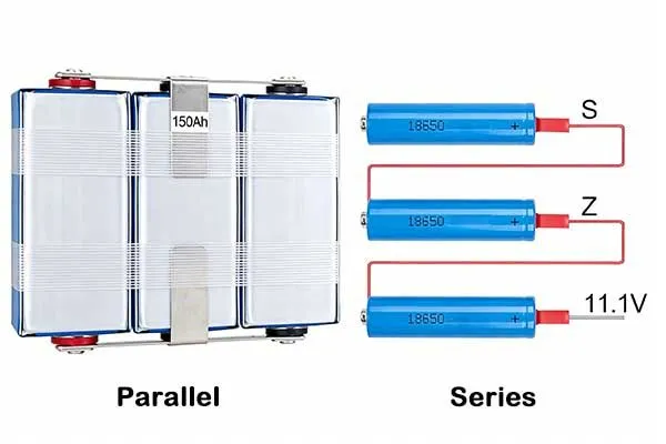
Batteries in series vs parallel change how voltage and current scale in a pack: series connections add voltage at constant ampere-hour capacity[1], while parallel connections add capacity at constant voltage.
Both can deliver similar total energy if cell count is the same, but their behavior under load, fault, and aging is very different, which makes wiring topology a core engineering choice in high‑reliability lithium‑ion systems.
Engineers can use structured design rules, BMS control, and pack‑level simulations to convert these circuit choices into safe, efficient, and scalable battery architectures for mobility and energy storage projects.
Table of Contents
- 1. What is the Difference Between Series and Parallel Battery Connections?
- 2. How Do Series and Parallel Connections Affect Voltage and Capacity?
- 3. Which Configuration Should You Choose for Your Battery System?
- 4. What are the Critical Engineering Trade-offs When Designing Battery Packs?
- 5. How are These Configurations Applied in Real-World Industrial Scenarios?
- 6. What are the Essential Design Guidelines for Safe and Efficient Integration?
- 7. Common Design Mistakes
1. What is the Difference Between Series and Parallel Battery Connections?
For lithium-ion packs, a series circuit connects cells end-to-end so voltages add while current rating stays equal to one cell, whereas a parallel circuit ties all positives together and all negatives together so capacity and current rating add while voltage stays at one cell.
Engineers choose between series vs parallel circuits to hit required pack voltage and ampere-hours while respecting limits on insulation, cabling, and power electronics.
Core circuit concepts
A series circuit has one current path and the same current (I) flows through every element, with total resistance
Rseries = R1 + R2 + …
In a parallel circuit, nodes share the same voltage, current splits into branches, and equivalent resistance follows as formula below, which always yields lower resistance than the same elements in series.
1/Rparallel = 1/R1 + 1/R2 + …
Current is defined as charge per unit time through a path, a node is a junction where currents sum, and impedance generalizes resistance when we include frequency‑dependent elements, we still mostly use simple Ohm’s law (V = IR) for DC pack analysis.
The difference between series and parallel circuits appears immediately: a series circuit raises voltage and total resistance, while a parallel circuit keeps voltage fixed but increases available current and reduces overall resistance, which directly shapes how batteries in series vs parallel behave during load spikes and faults.
For resistance in series vs parallel, this means series strings naturally limit current, while parallel networks allow higher current and demand tighter current sharing control.
Key formulas table
| Quantity | Series circuit | Parallel circuit |
|---|---|---|
| Voltage | Vtotal = V1 + V2 + … | Same across branches, V1 = V2 = … |
| Current | Same through all elements | Sum of branch currents, (I = I1 + I2 + … |
| Resistance | Rseries = R1 + R2 + … | 1/Rparallel = 1/R1 + 1/R2 + … |
| Power dissipation trend | Lower total current for same voltage | Higher total current for same voltage |
From circuits to battery packs
When engineers talk about series vs. parallel circuits for lithium packs, they usually mean series strings of cells that set pack voltage and parallel groups that set pack current and capacity.
A series circuit of cells defines the nominal DC bus that inverters or DC‑DC converters must handle, while a parallel circuit of identical cells defines how much surge current and runtime the pack can support without overstressing individual cells.
Tips
Voltage defines efficiency, but current defines heat. Always evaluate both together when selecting series vs parallel configurations.
In batteries in series vs parallel, series connection increases battery voltage vs capacity series parallel by stacking cell voltages, whereas parallel vs series connections increase ampere-hour capacity and reduce effective impedance.
For engineers comparing in series vs in parallel configurations, the practical question is usually not which is “better” but how to combine them into a safe li‑ion battery pack configuration that meets voltage, current, and thermal limits simultaneously.
Build Your Battery Architecture Right from Day One
Engineer-verified pack design support
2. How Do Series and Parallel Connections Affect Voltage and Capacity?
In practical series vs parallel circuits built from lithium cells, series wiring raises pack voltage and total resistance so current is lower for the same load, while parallel wiring holds voltage constant but reduces resistance and raises current, which means parallel vs series circuit choices directly shape cable sizing, contact heating, and protection thresholds in real packs.
Voltage, current, and power behavior
In series vs parallel wiring, the total system power (P = VI) can be similar for different topologies, but current and voltage stress move between conductors and insulation.
For instance, doubling series cell count doubles voltage and roughly halves current at the same power, so cabling losses Ploss = I2R fall sharply, while insulation and creepage requirements rise.
For series vs parallel circuits, a given set of resistive loads draws less current when wired in series than in a parallel circuit at fixed supply voltage, because the equivalent resistance is higher in series and lower in parallel.
As a result, parallel circuit topologies deliver more current and power but require good control of branch currents to avoid local overheating, which is crucial for batteries in series vs parallel under uneven cooling.
This also underpins battery voltage vs capacity series parallel decisions: high‑voltage strings reduce conduction losses, while parallel groups boost capacity and peak power at the expense of more complex current sharing.
Electrical behavior table
| Aspect | Series battery string | Parallel battery group |
|---|---|---|
| Voltage | Adds with each cell | Equals single‑cell voltage |
| Capacity (Ah) | Same as one cell | Sum of parallel cells |
| Conduction losses | Lower at high voltage | Higher due to higher current |
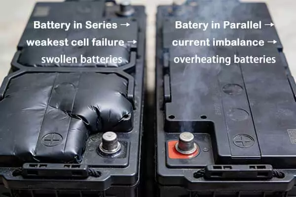
| Fault impact | Weak cell limits whole string | Branch imbalance causes hot spots |
Implications for lithium packs
Our experience at Long Sing Energy shows that many field failures come from ignoring how series vs parallel wiring alters both fault modes and maintenance paths in large packs used for RV, solar, and ESS projects.
When engineers build packs with heavy series vs parallel battery combinations, a single underperforming cell in a series string can cap usable capacity, while poor busbar design in parallel blocks can create uneven current and unexpected aging.
In batteries in series vs parallel, the equivalent impedance and local heat generation must be mapped before finalizing the layout, especially for high‑power tools and electric mobility where vibration and temperature gradients are harsh.
Careful modeling of parallel vs series conductor routing, fuse locations[2], and BMS sensor placement turns these basic circuit differences into predictable, controllable behavior under both nominal and fault conditions.
3. Which Configuration Should You Choose for Your Battery System?
In battery systems, engineers combine series vs parallel battery connections into structured modules and packs so that series strings define the DC bus voltage while parallel groups define energy capacity and peak current, and the overall architecture must support cell balancing, fault isolation, and maintainability across the full operating life.
Pack topology and configuration
A typical li-ion battery pack configuration for mobility or ESS uses multiple cells in series to reach system voltage, then multiple strings in parallel to reach capacity and current rating.
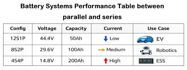
For example, batteries in series vs parallel can be arranged as 4S2P or 2P4S; both may hold similar energy, but thermal behavior, busbar layout, and BMS channel count differ.
Battery Series & Parallel Calculator
Total Voltage
– V
Total Current
– A
Pack Config
–
In solar storage, designers often build higher voltage banks by wiring 12 V modules in series, then parallel‑connecting series strings to scale usable ampere-hours, a standard approach in series vs parallel wiring of lead‑acid and lithium systems alike.
A published example uses eight 12 V 100 Ah LiFePO₄ units where pairs are paralleled first and then these pairs are placed in series, which illustrates a mixed series vs. parallel wiring approach to meet specific voltage and capacity requirements for solar systems.
This kind of mixed batteries in series vs parallel layout is also common in RV and light EV platforms that we supply as a lithium ion battery manufacturer.
Module and pack structure table
| Level | Series role | Parallel role |
|---|---|---|
| Cell | Defines basic voltage and capacity | N/A |
| Parallel block | Adds capacity, lowers impedance | Enables high current and redundancy |
| Series string | Sets DC bus voltage | N/A |
| Pack | Aggregates strings; defines system voltage window | Scales total energy for application |
Balancing and BMS interaction
In series strings, mismatched cells drift in state of charge over time, so lithium ion battery balancing inside the BMS becomes critical to maintain usable capacity and avoid overcharge on the strongest units.
Modern research shows that advanced BMS algorithms can transfer charge between serially connected cells to mitigate SoC inconsistencies[3] and prevent the weakest cell from limiting pack capacity.
For parallel groups, cell balancing in parallel modules is more subtle because cells share a common node and tend to equalize voltage passively, yet manufacturing tolerances and temperature gradients still create unequal current distribution that a good BMS must monitor.
Engineers who consider in series vs in parallel only at schematic level often underestimate how mechanical layout and cooling produce divergence that software alone cannot fix, especially when many parallel vs series branches overlap in large ESS cabinets.
Custom Pack Configuration for Your Application
Tailored voltage and capacity solutions
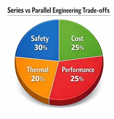
4. What are the Critical Engineering Trade-offs When Designing Battery Packs?
Engineers face trade-offs between higher‑voltage series configurations that reduce current and cabling losses versus higher‑capacity parallel configurations that enhance runtime and redundancy but complicate current sharing and thermal control, so every batteries in series vs parallel choice must balance ROI, safety, and maintainability.
Efficiency, safety, and ROI
From a system perspective, more cells in series circuit configurations improve efficiency because current drops for the same power, which reduces conductor cross‑section requirements and lowers resistive losses. This supports a favorable ROI in stationary ESS and large solar banks, where greater series count can reduce copper cost and busbar bulk if insulation and clearances are well engineered.
On the other hand, more cells in parallel circuit arrangements increase total capacity and allow higher burst currents, which is attractive in power tools, UAVs, and electric mobility but demands careful design to prevent one branch from carrying disproportionate current.
When engineers compare parallel vs series economically, they must weigh the savings from series‑driven cable downsizing against the additional contactors, fuses, and monitoring points needed to keep parallel blocks safe and balanced in large installations.
ROI and design factor table
| Factor | Favoring more series | Favoring more parallel |
|---|---|---|
| Cable and busbar cost | Lower current, cheaper conductors | Higher current, heavier conductors |
| Converter / inverter design | Better efficiency at high DC voltage | Lower voltage electronics but higher current rating |
| Fault tolerance | String limited by weakest cell | Branches provide partial redundancy |
| Thermal management | Fewer high‑current nodes | More local hot spots, complex mapping |
Failure modes and protection
Different series vs parallel circuits amplify different failure modes: one failing cell in a long series string can cause under‑voltage traps or overcharge in neighbors, whereas a failing cell in a large parallel group can sink or source excessive current relative to its peers.
Protection circuits and BMS logic must therefore consider these specific patterns when deciding where to place sensors, how to size fuses, and what trip thresholds to use for batteries in series vs parallel.
Modern protection circuits detect abnormal voltage or temperature and disconnect the pack to prevent thermal runaway and fires, which is especially important at high series voltages where energy is large and fault propagation can be rapid.
For parallel groups, engineers must constrain fault currents through judicious busbar geometry, current‑limiting elements, and fast‑acting switches, because purely relying on series vs parallel wiring without current limiting can overwhelm even robust cells during internal shorts.
Balance Cost, Safety, and Performance Precisely
ROI-focused engineering decisions
5. How are These Configurations Applied in Real-World Industrial Scenarios?
In real projects like RVs, solar ESS, and automated production equipment, practical batteries in series vs parallel designs use mixed series‑parallel topologies with strong BMS supervision, detailed thermal mapping, and strict manufacturing control to avoid even a single defective cell and to keep current distribution uniform across all branches.

Application patterns: RV, solar, ESS
For RV and marine customers, higher‑voltage packs wired with more series cells and limited parallel strings reduce current through long cable runs, which cuts copper weight and improves inverter efficiency during boondocking.
In rooftop solar ESS, installers usually prefer series vs parallel circuits that prioritize series strings for voltage, then use a limited number of parallel strings to scale capacity, because excessive parallel vs series branching complicates fault detection and maintenance.
Industrial ESS cabinets often parallel multiple high‑voltage racks, each rack already built from mixed batteries in series vs parallel modules, which makes pack‑to‑pack balancing and protection a system‑level challenge rather than a simple cell‑level task. In these projects, our team, led by chief engineer Jack Song, usually recommends a clear hierarchy of series strings, module fuses, and pack contactors so that faults remain local and serviceable.
Example topology table (conceptual)
| Use case | Typical series voltage target | Typical parallel strategy |
|---|---|---|
| RV / camper | 12–48 V bus via series cells | 1–4 parallel strings for capacity |
| Residential ESS | 48–200 V nominal | 2–6 parallel strings depending on kWh target |
| Industrial ESS | 400–800 V DC link | Multiple parallel racks with supervisory controls |
German automation case: thermal gradient and fire prevention
A German automation equipment company asked us to redesign their high‑voltage lithium pack because they observed strong thermal gradients[4] between modules, uneven aging, and a small but unacceptable fire risk in a robotics production line.
Their original pack used long series strings with multiple parallel blocks per layer, but cooling channels favored some modules while others ran hotter during charge‑heavy cycles.
We proposed a pack where each module used a clear series vs parallel wiring pattern: fixed‑length series chains of prismatic NMC cells(3.7V 50Ah) for voltage, combined with limited parallel grouping(8S2P) to meet current goals, and uniform coolant plate coverage across all modules.
We implemented parallel current simulation and thermal mapping during design, so we visualized how parallel vs series circuit layouts affected local temperature and current density[5] across different duty cycles.
To avoid thermal runaway and fire, we integrated multi‑level protection circuits and BMS logic that monitored per‑cell voltage and temperature and disconnected the pack if any cell exceeded safe thresholds.
Manufacturing controls enforced tight cell matching so statistical spreads in capacity and impedance [6] were very small, which reduced balancing effort and practically eliminated the chance that even one bad cell would slip into a series string.
Tips
Balancing is not just correction—it is prevention. Proper balancing design extends battery life significantly.
We also used advanced lithium ion battery balancing algorithms that combined passive bleed at the top of charge with active redistribution between modules, so strings remained aligned even under uneven loading.
This design, with careful batteries in series vs parallel architecture, balanced cable cost, thermal uniformity, and safety, and it demonstrates how rigorous simulation plus disciplined assembly can turn fundamental circuit choices into robust industrial systems.
Proven Battery Solutions for Industrial Systems
Real cases, real performance results
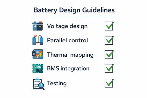
6. What are the Essential Design Guidelines for Safe and Efficient Integration?
Robust lithium packs depend on deliberate choices of series vs parallel wiring, conservative BMS thresholds, and physically symmetric layouts that keep electrical, thermal, and mechanical conditions as uniform as possible across all cells and modules.
Practical rules for series and parallel
Engineering teams should treat series vs parallel battery decisions as power‑train choices, not just wiring details: define target bus voltage first, then derive the minimum series count compatible with converter and insulation limits.
Once the series stack is fixed, select the minimum number of parallel strings that meets peak current and energy targets, because reducing parallel branches simplifies current sharing and fault analysis in series vs. parallel circuits inside a large pack.
Mechanical design should enforce equal path resistance for all parallel branches, with mirrored busbars[7] and consistent lug lengths, because unequal path resistance drives imbalanced currents even when cells are identical.
Engineers should revisit earlier assumptions about batteries in series vs parallel whenever they change enclosure geometry, cooling layouts, or connector positions, since these changes silently modify resistance networks and thermal gradients.
Design checklist table
| Design area | Key guideline |
|---|---|
| Voltage and series | Set bus voltage first; design minimum safe series count |
| Parallel scaling | Use few, symmetric strings for capacity |
| Busbar layout | Equalize resistance in all branches |
| Cooling | Map temperature across all modules, minimize gradients |
| Testing | Validate with current and thermal mapping under worst‑case cycles |
BMS roles and selection
A capable BMS must supervise every series cell for voltage, monitor temperature throughout the pack, and, where possible, estimate branch currents in parallel networks to detect imbalance before it becomes dangerous.
For mixed series vs parallel wiring designs, engineers should choose a BMS that supports sufficient cell channels, robust balancing current, and clear strategies for string‑level isolation and diagnostics.
For large packs, li-ion battery pack configuration and BMS hardware must evolve together: more series elements require higher isolation voltages and careful communication architecture, while more parallel elements demand better algorithms for detecting and mitigating hidden branch faults.
When we discuss BMS options with customers, we recommend considering balancing current sizing according to expected leakage and pack size, because under‑sized balancing reduces lifetime and over‑sized hardware inflates cost without improving real‑world performance.
7. Common Design Mistakes
Many issues with batteries in series vs parallel arise from simplistic assumptions about current sharing, cell matching, and balancing limits, so engineers should deliberately avoid over‑paralleling, neglecting thermal gradients, or assuming the BMS can mask poor mechanical and electrical design.
Typical pitfalls in series and parallel packs
One common mistake is excessive parallelization at low voltage to avoid high‑voltage design work, which drives up current, increases copper cost, and amplifies sensitivity to small resistance differences between branches.
Another is assuming that parallel connections automatically equalize everything; in reality, impedance variations and temperature differences can cause some cells to carry more current and age faster, even in apparently symmetric parallel circuit networks.
On the series side, designers sometimes stretch series strings close to the limit of converter ratings without leaving margin for cell voltage spread, which reduces lifetime and increases the risk that over‑charge protection will trip early.
Others underestimate how one weak cell affects the entire string, especially in long series circuit arrangements, so they do not invest enough in incoming cell screening and traceability for batteries in series vs parallel used in mission‑critical ESS or mobility installations.
Mistake and mitigation table
| Mistake | Consequence | Mitigation |
|---|---|---|
| Too many parallel branches | Uneven currents, higher copper cost | Limit branches, equalize path resistance |
| Relying only on parallel equalization | Hidden aging differences | Use monitoring and thermal mapping |
| Overlong series strings | Tight margins, early trips | Leave voltage margin, strong balancing |
| Weak cell screening | String limited by one cell | Tight QA and matching, robust BMS |
Integrating fundamentals into practice
Engineers who deeply understand difference between series and parallel circuits at the resistor level apply the same logic to packs by thinking in terms of impedance networks and heat sources instead of only schematic symbols.
When they choose between parallel vs series configurations for a new product, they frame it as a system optimization across voltage, current, ROI, and safety rather than a narrow electrical decision.
By grounding design work in clear fundamentals of in series vs in parallel behavior, robust BMS strategies, and realistic manufacturing constraints, teams can build lithium packs that meet demanding mobility, solar, and ESS requirements with predictable performance over many years.
Avoid Costly Battery Design Failures
Prevent issues before mass production
Conclusion
In lithium‑ion projects, engineers use batteries in series vs parallel to independently tune voltage and capacity, but every choice reshapes current, resistance, thermal behavior, and failure modes across the pack. High‑voltage series strings reduce conduction losses and support efficient converters, while well‑controlled parallel groups deliver the capacity and surge current that vehicles, RVs, solar ESS, and industrial equipment require.
Strong BMS hardware and balancing algorithms, thorough cell matching, careful busbar and cooling layout, and realistic ROI analysis ensure that even complex series vs parallel wiring remains safe and reliable throughout the pack’s life.
Frequently Asked Questions
Click to explore more information about batteries in series vs parallel
Q: How to tell parallel vs series?
A: You can identify the wiring by looking at the terminals. In series, the positive terminal of one battery is connected to the negative terminal of the next. In parallel, all positive terminals are connected together, and all negative terminals are connected together.
Q: Are 12V batteries better in series or parallel?
A: It depends on your application. Series is better if you need to power high-voltage equipment (e.g., a 24V or 48V motor), as higher voltage reduces current draw and allows for thinner wiring. Parallel is better if you need to extend the runtime of 12V electronics without changing the system voltage.
Q: Is the voltage higher in series or parallel?
A: Voltage is higher in a series circuit. For example, two 12V batteries in series produce 24V. In a parallel circuit, the voltage remains at the baseline of 12V regardless of how many batteries are added.
Q: Will 2 12V batteries in parallel last longer?
A: Yes. Connecting batteries in parallel increases the total Amp-hour (Ah) capacity. If you have two 100Ah batteries in parallel, you create a 200Ah bank, effectively doubling the runtime for your 12V devices compared to a single battery.
Q: Is it better to connect in series or parallel?
A: Neither is universally “better”; it is about matching your load requirements. Use series to meet the voltage requirements of your inverter or motor. Use parallel to increase the energy storage and current capacity for longer-lasting power.
Q: How does series vs. parallel wiring work?
A: Series wiring creates a single path for electrons to flow through all components, summing their electrical pressure (voltage). Parallel wiring creates multiple paths, allowing the total current to be divided among the branches, which increases the total volume of energy available without increasing the pressure.
Q: Would someone mind simply explaining the pros and cons of series vs parallel?
A: Series Pros: Higher voltage, higher efficiency for heavy loads, thinner cables. Series Cons: If one battery fails, the whole circuit breaks. Parallel Pros: Longer runtime, redundant reliability (if one fails, others keep working), maintains lower voltage. Parallel Cons: Requires thicker cabling to handle higher combined current.
Reference:
[2]Learn where fuses should be placed to isolate faults and prevent cascade failures.↪
[3]Learn about balancing methods that prevent capacity loss and weak-cell isolation in strings.↪
[4]Understand how thermal gradients impact battery safety and aging in high-voltage systems.↪
[5]Understand how current density affects heat generation and battery lifespan.↪
[6]Learn how impedance variations lead to imbalance and uneven aging in packs.↪
[7]Explore how busbar design impacts resistance, efficiency, and thermal behavior.↪